System development planning tool

a system development and planning tool technology, applied in the field of system development planning tools, can solve the problems of time-consuming and difficult to complete the development of complex software systems, customers often do not have a firm idea of all their requirements, and frustration for both software developers and their customers

Inactive Publication Date: 2005-05-26
QWEST
View PDF9 Cites 73 Cited by
  • Summary
  • Abstract
  • Description
  • Claims
  • Application Information

AI Technical Summary

Problems solved by technology

Development of complex software systems tend to be time consuming and difficult to complete because of frequently changing customer requirements.
Unfortunately, customers often do not have a firm idea of all their requirements until after development has started.
Also, changing business needs will often dictate changes in system requirements as the software development project is underway.
The result is often frustration for both software developers and their customers.
Customers, on the other hand, desire (and sometimes feel compelled to make) changes in requirements as their needs change, especially in large projects where at the end of a development period the needs of a business may have change so dramatically from those in the beginning, that the end work product will be outdated and not useful if the requireme

Method used


Image

  • System development planning tool
  • System development planning tool
  • System development planning tool

Examples


Embodiment Construction

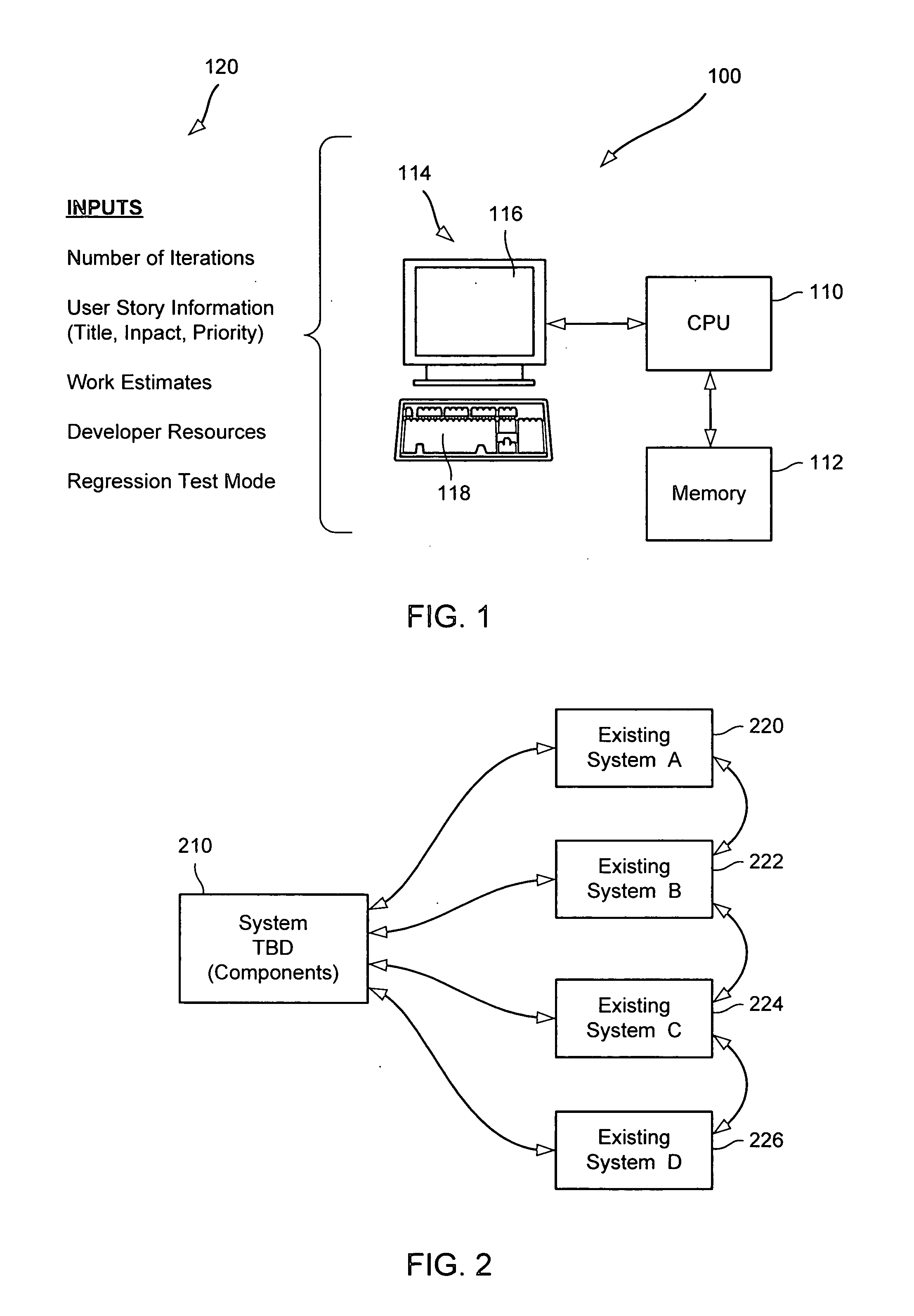
[0016] There are various embodiments and configurations for implementing the present invention. On such implementation is shown in FIG. 1, where according to an embodiment of the invention, a system 100 is programmed to operate as a tool for use in the planning or management of a software development project. The system 100 includes a CPU 110 that executes software programs implementing the project management process, a memory 112 for storing data and programs used in the process, and a user interface 114 (illustrated as a PC monitor or display screen 116 and an associated keyboard 118) for enabling a user (project manager) to plan and manage the development project.

[0017] As illustrated in FIG. 1, various kinds of information 120 relating to the development project is entered by the project manager at the user interface 114. Such information (inputs) will be described in greater detail later, but as illustrated in FIG. 1 it includes:

[0018] Number of Iterations—The number of itera...


PUM


Abstract

A system for planning and managing a software development project uses an extreme programming (XP) process and includes a graphical user interface (GUI) for displaying graphs and for entering, displaying and modifying underlying planning data. In one embodiment, the GUI includes first, second and third windows. The first window displays bar graphs reflecting both estimated development work and available resources (developer hours) for working on development. The second window displays bar graphs representing both estimated testing work and available resources for working on testing. The third window displays underlying data (e.g., project components and assignment of project components to scheduled development periods). A project manager may use the third window to adjust underlying data in order to better balance work and resources displayed in the first and second windows. Additional underlying data (individual developers, assigned hours, estimates of work on individual project components, etc.) may be displayed in other windows.

Description

CROSS-REFERENCES TO RELATED APPLICATIONS [0001] NOT APPLICABLE STATEMENT AS TO RIGHTS TO INVENTIONS MADE UNDER FEDERALLY SPONSORED RESEARCH OR DEVELOPMENT [0002] NOT APPLICABLE REFERENCE TO A “SEQUENCE LISTING,” A TABLE, OR A COMPUTER PROGRAM LISTING APPENDIX SUBMITTED ON A COMPACT DISK [0003] NOT APPLICABLE BACKGROUND OF THE INVENTION [0004] Development of complex software systems tend to be time consuming and difficult to complete because of frequently changing customer requirements. Traditional software development project management theory often mandates the creation of a “requirements” document that describes the functionality and features of the software system to be developed. A software development organization will create the requirements document based on input from the customer, and then have the customer approve the document so as to “lock” in the expectations of the customer and conduct the development work against a plan that does not change. [0005] Unfortunately, cust...

Claims


Application Information

Patent Timeline
IPC IPC(8): G06F9/44
CPCG06F8/10
Inventor KNUTSON, JEF W.HILGERT, PHILLIP
Owner QWEST
Why Eureka
Try Eureka