Clamping clip for bundled sinuous wire

a technology of bundled sinuous wire and clamping clip, which is applied in the direction of hose connection, flexible elements, packaging, etc., can solve the problems of user difficulty in separating the bundle at the desired time of separation, laborious and extremely costly methods, and loose wires, so as to reduce the associated labor costs, improve efficiency and cost savings, and install and remove quickly

Inactive Publication Date: 2005-06-02
HICKORY SPRINGS MFG
View PDF14 Cites 0 Cited by
  • Summary
  • Abstract
  • Description
  • Claims
  • Application Information

AI Technical Summary

Benefits of technology

[0006] It is accordingly an object of the present invention to provide a device and a method for clamping together in bundled form a plurality of sinuous wires. More particularly, it is the object of the present invention to provide a device that can be installed and removed quickly without the aid of any tools, thereby, reducing the associated labor costs. Another object of the present invention is to provide a device and method that can ultimately be mechanized, further improving the efficiency and cost savings associated with the device and method.

Problems solved by technology

Disadvantageously, this method is labor intensive and extremely costly.
Further, if the flexible wire is not sufficiently wrapped or tied around the bundle of wires, the wires can readily separate resulting in loose wires.
On the other hand, if the flexible wire is wrapped or tied too tightly around the bundle of wires, a user may have difficulty separating the bundle at the desired time of separation.
However, none of these devices and apparatuses relate to a clip device for clamping a plurality of sinuous wires.
Therefore, until now, there has not been a device or a method for quickly and efficiently, manually clamping a plurality of sinuous wires into a bundle.

Method used


Image

  • Clamping clip for bundled sinuous wire
  • Clamping clip for bundled sinuous wire
  • Clamping clip for bundled sinuous wire

Examples


Embodiment Construction

[0022] The present invention will be described more fully hereinafter with reference to the accompanying drawings, in which preferred embodiments of the invention are shown. This invention may, however, be embodied in many different forms and should not be construed as being limited to the embodiments set forth herein. Rather, these embodiments are provided so that this disclosure will be thorough and complete and will fully convey the scope of the invention to those skilled in the art.

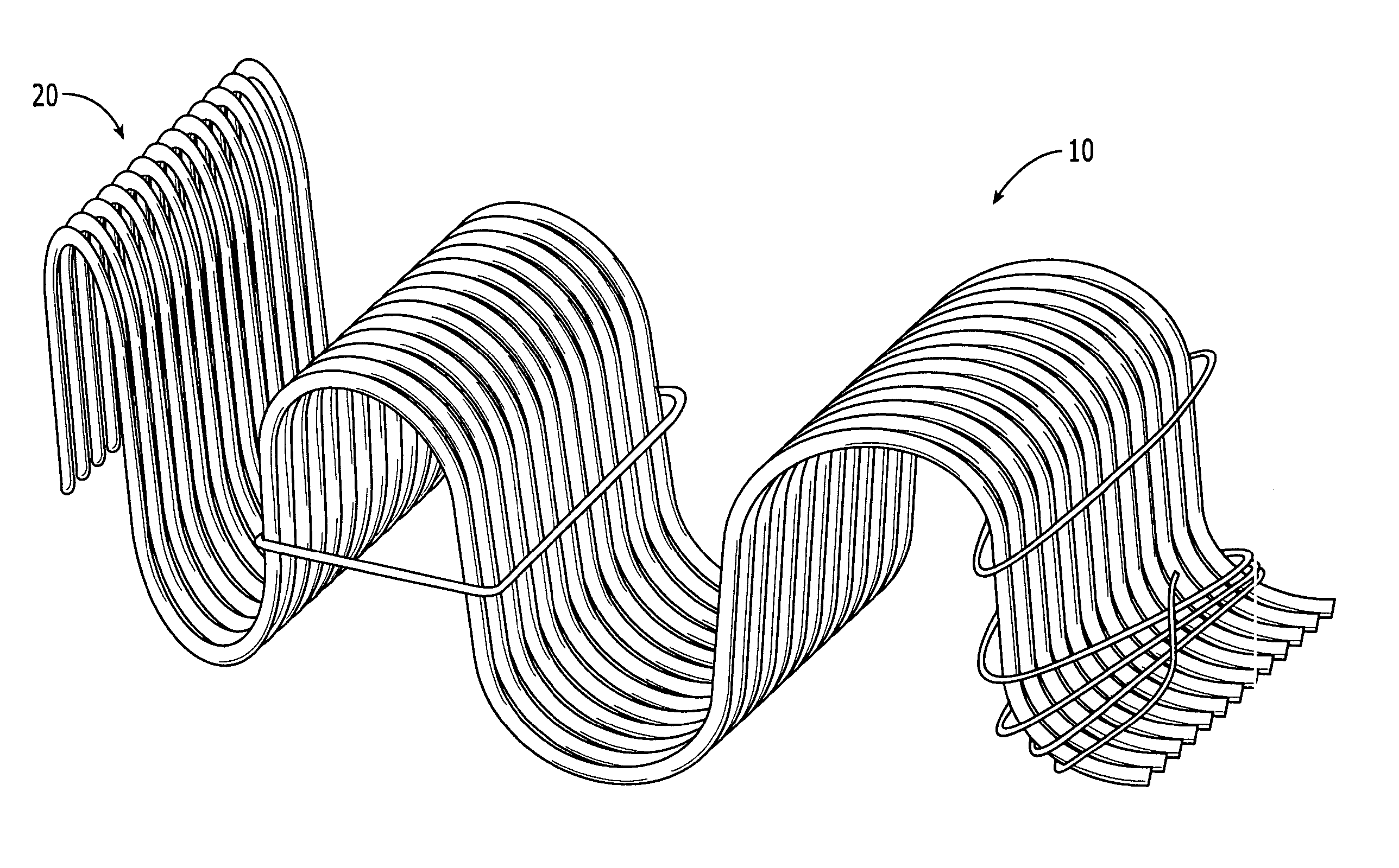
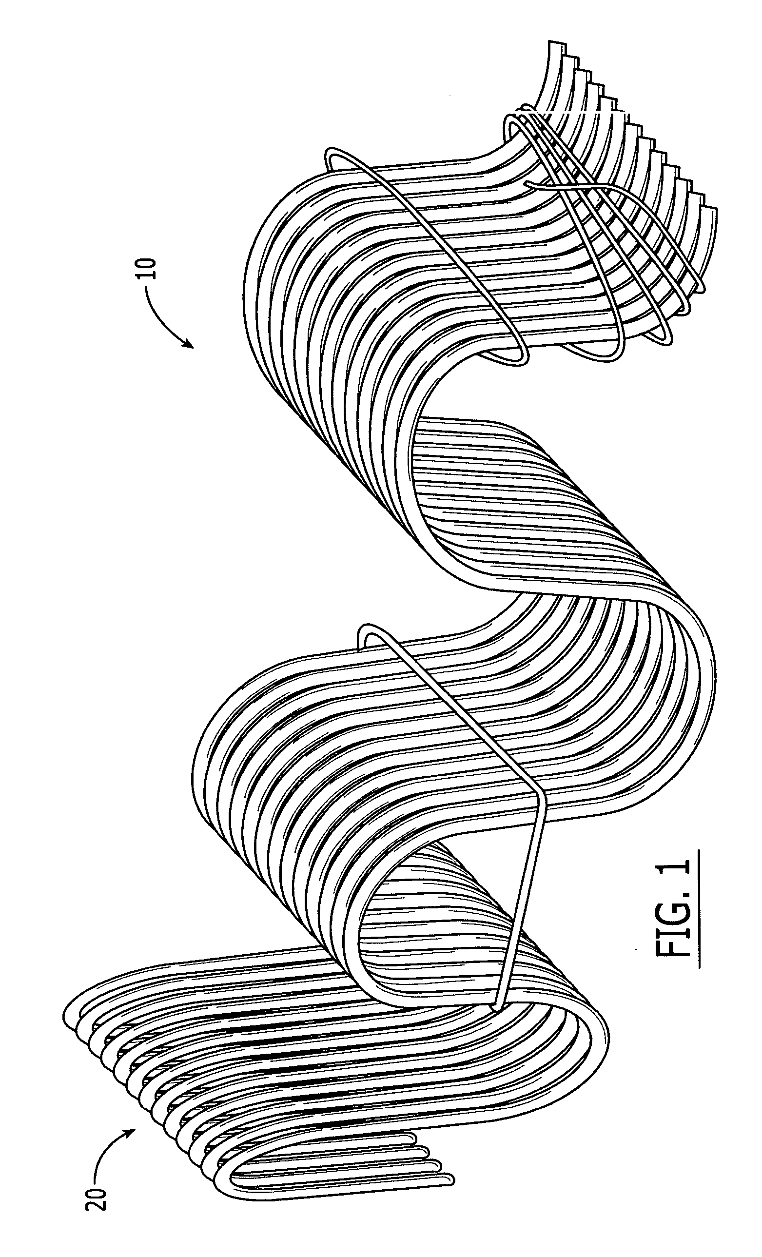
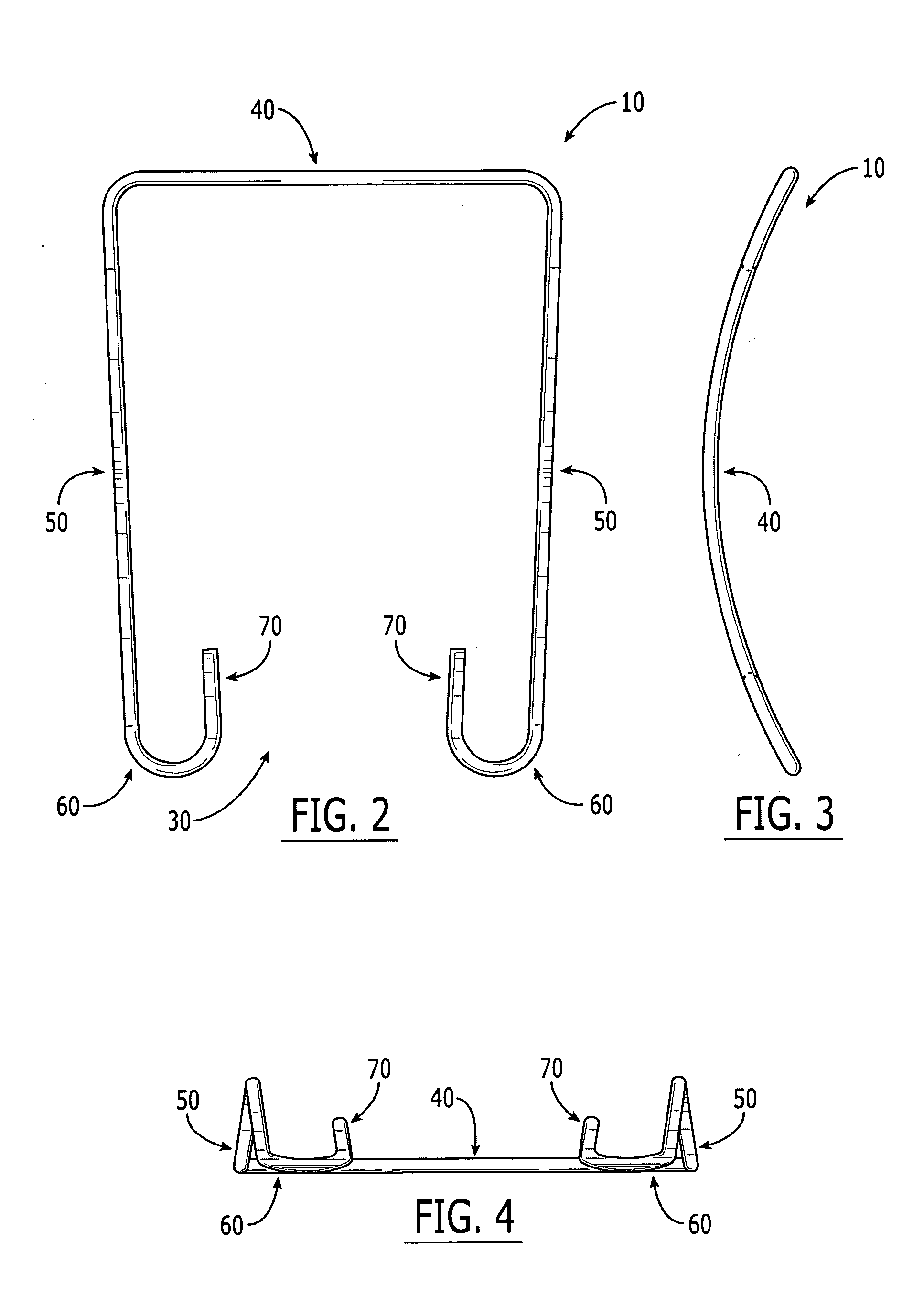
[0023] Turning now to the accompanying drawings and initially FIG. 1, the clip device in accordance with the present invention is illustrated in its totality at 10 and is shown clamping together in bundled form a plurality of sinuous wires 20. The clip device 10 is formed from a single continuous piece of wire having a generally U-shaped configuration. As illustrated in FIG. 2, the clip device 10 has an open end 30 and a closed end 40. The closed end 40 forms the base portion 40 of the clip device 10...


PUM


Abstract

A clip device and a method for clamping together in bundled form a plurality of sinuous wires, wherein the clip device is formed from a single continuous piece of wire having a generally U-shaped configuration with an open end and a closed end, the closed end forming a base portion and the open end being formed by a pair of legs extending away from the base portion with each said leg having an end portion bending inwardly toward the base portion to form a pair of hooks, and the method comprising the steps of: (a) gathering a plurality of sinuous wires into a bundle; (b) compressing the bundle; (c) aligning the loops in the bundle; (d) installing the clip device; (e) stacking a clamped bundle on a pallet; (f) heating the stacked, clamped bundles in an oven; and (g) packaging the clamped bundles.

Description

FIELD OF THE INVENTION [0001] The present invention relates generally to a device for clamping together in bundled form a plurality of sinuous wire in stacked relationship to one another. BACKGROUND [0002] Sofas, chairs and other similarly related furniture are typically comprised of sinuous wires that are used to provide a support structure for the seat bottoms and backs of such furniture. These springs are commonly shipped and stored in bundles that are generally formed by bundling a plurality of sinuous wires together in stacked relationship to one another and manually securing the wires to one another. [0003] The conventional method for clamping a bundle of a plurality of sinuous wires together is to manually wrap or tie a length of flexible wire around the bundle of wires. Disadvantageously, this method is labor intensive and extremely costly. Further, if the flexible wire is not sufficiently wrapped or tied around the bundle of wires, the wires can readily separate resulting i...

Claims


Application Information

Patent Timeline
Patent Type & Authority Applications(United States)
IPC IPC(8): B65D63/00B65D63/02
CPCY10T24/149B65D63/02
Inventor POWELL, LARRY D.BUTLER, MELVIN E.LAIL, JEFFERY L.
Owner HICKORY SPRINGS MFG
Why Eureka
Try Eureka