Suction and filtering apparatus

a filtering apparatus and air suction technology, applied in the direction of cleaning equipment, dispersed particle separation, separation processes, etc., can solve the problems of reducing the efficiency of the filtering power, dampening the air and fine dust, and affecting so as to prevent the formation of damp dirt deposits, the effect of reducing the nebulization of water and absorption of fine particles

Inactive Publication Date: 2005-06-02
DE LONGHI SPA
View PDF4 Cites 3 Cited by
  • Summary
  • Abstract
  • Description
  • Claims
  • Application Information

AI Technical Summary

Benefits of technology

[0013] One purpose of the invention is to achieve an air suction and filtering apparatus by means of which it is possible to completely separate the dust and the solid particles sucked in together with the air and, at the same time, to prevent the formation of unwanted deposits of said dust and solid particles.
[0016] Advantageously, the water introduction means are able to create a vortical motion of the water in the mixing chamber, so as to facilitate the nebulization of the water and the absorption of the finer particles.
[0017] The apparatus according to the invention thus allows to separate the heaviest and / or largest particles in the dry filter, and subsequently, in the mixing chamber, to dampen the air with an injection of water, making the finer particles heavier, so as to encourage them to fall into the liquid bath filter.
[0018] With the apparatus according to the invention it is also possible to prevent the formation of deposits of damp dirt. In fact, the water to be introduced and mixed with the air sucked in arriving from the dry filter cleans the zones of passage of the air between the dry filter and the liquid bath filter.
[0021] Advantageously both the water introduction means to introduce the water into the mixing chamber and also the inlet pipe to introduce the air arriving from the dry filter are arranged in proximity with the circular wall, so that both the water and the air are fed in a peripheral zone of the mixing chamber along the circular wall. On the contrary, the outlet pipe, which conveys the mixture of water outside the mixing chamber towards the liquid bath filter, is made in a central zone on one of the two lateral walls of the chamber itself. This configuration allows the formation of the aforementioned vortical motion of the mixture of air-water, from the peripheral zone towards the central zone of the mixing chamber.

Problems solved by technology

This known apparatus has the disadvantage, however, that the air and finer dust, which do not deposit in the liquid bath filter, are partly dampened by the water contained therein.
The dampened air and dust unfortunately dampen the dry filter too, and damage it, with the risk that the efficiency of its filtering power can be diminished.
Moreover, the dampened air and dust also cause the formation of damp deposits, which are difficult to remove, in the zone of passage between the liquid bath filter and the dry filter.
This known apparatus has the disadvantage, however, that, in the intermediate zone between the dry filter and the liquid bath filter, the air sucked in is in no way made heavier, or dampened, in order to encourage the dust to fall through gravity into the liquid bath.

Method used


Image

  • Suction and filtering apparatus
  • Suction and filtering apparatus
  • Suction and filtering apparatus

Examples


Embodiment Construction

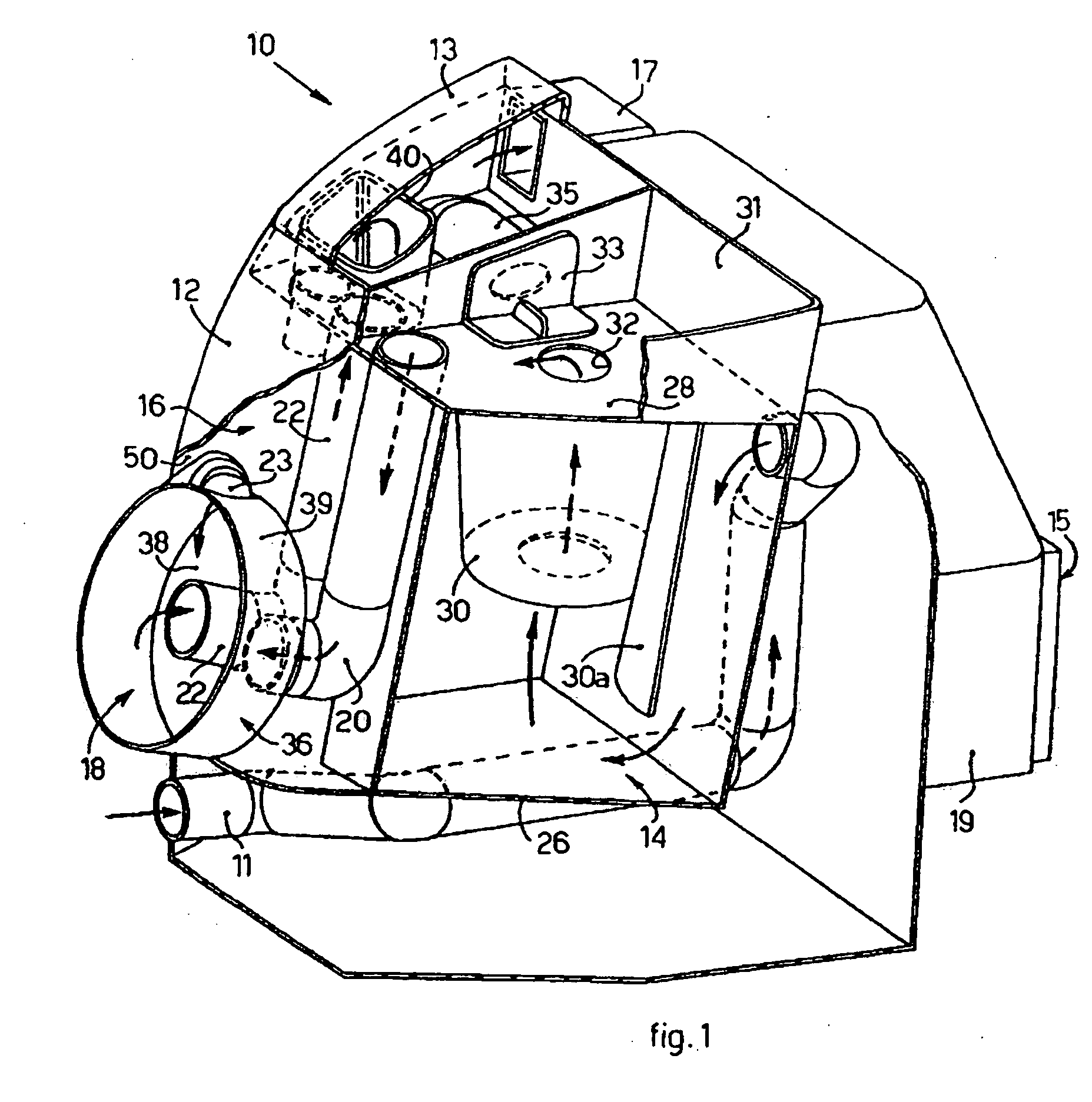
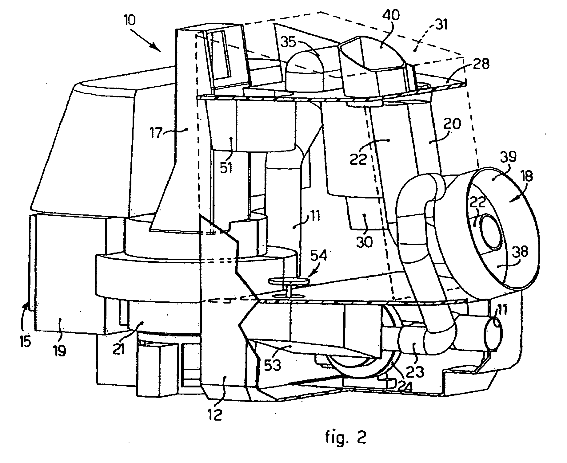
[0036] With reference to the FIGS. 1 and 2, a suction and filtering apparatus 10 according to the present invention comprises an inlet pipe 11 for the introduction of the air sucked in, an outlet aperture 15 for the filtered air and a suction motor 21 arranged between the inlet pipe 11 and the outlet aperture 15 in order to create a corresponding flow of air.

[0037] The apparatus 10 also comprises a tank 12, closed at the top by means of a cover 13, inside which a first filtering unit is made, comprising a dry filter 14, and a second filtering unit, comprising a liquid bath filter, or water filter 16. The latter is connected to the suction motor 21 by means of an intermediate pipe 17. Between the suction motor 21 and the outlet aperture 15 there is also a unit to expel the air 19, provided with another filter device of a known type, for example a HEPA filter.

[0038] According to a characteristic of the present invention, the apparatus 10 also comprises a mixing chamber 18, independe...


PUM

PropertyMeasurementUnit
pressureaaaaaaaaaa
shapeaaaaaaaaaa
suctionaaaaaaaaaa

Abstract

Air suction and filtering apparatus, comprising a dry filter (14) and a liquid bath filter (16), connected together in series, and suction means (21) able to create a flow of air between an inlet pipe (11), through the dry filter (14) and the liquid bath filter (16), and an outlet aperture (15), arranged downstream of the liquid bath filter (16). Between the dry filter (14) and the liquid bath filter (16) a mixing chamber (18) is arranged, independent of the two filters (14, 16), into which the air arriving from the dry filter (14) is able to be conveyed. The apparatus comprises a water introduction pipe (23), which is connected to the mixing chamber (18) in order to introduce water therein and obtain, in the mixing chamber (18), an air-water mixture able to be conveyed into the liquid bath filter (16).

Description

FIELD OF THE INVENTION [0001] The present invention concerns an air suction and filtering apparatus wherein the air sucked in is filtered of the dust and solid particles by means of a dry filter and a liquid bath filter. The two filters are arranged in series and a mixing chamber is made between them, in which the air, after being partly filtered in the dry filter, is mixed with a jet of clean water. The mixture of air and water thus obtained is conveyed into the liquid bath filter to make even the finer dust, which is more difficult to capture, precipitate therein. BACKGROUND OF THE INVENTION [0002] A suction and filtering apparatus is known, comprising a liquid bath filter containing water and, downstream, a dry filter. [0003] A suction motor is arranged downstream of the dry filter. In this way the motor is able to generate a flow to suck in the air and dust between an inlet and an outlet of the filtering apparatus, so that the air passes first in the water contained in the liqui...

Claims


Application Information

Patent Timeline
Patent Type & Authority Applications(United States)
IPC IPC(8): A47L9/16A47L9/18B01D47/02B01D50/00
CPCA47L9/1608A47L9/183B01D47/025B01D47/024B01D50/006B01D50/60
Inventor DI PIAZZA, GIORGIOSCIAN, LUCIANO
Owner DE LONGHI SPA
Why Eureka
Try Eureka