All-wheel drive electric vehicle

a technology of electric vehicles and electric vehicles, applied in the direction of electric devices, battery/fuel cell control arrangements, electric devices, etc., can solve the problems of electric vehicles having to be charged on the road constantly, the road is also disadvantageous, and the typical drive is not possibl

Inactive Publication Date: 2005-06-02
LANIER THEODORE D
View PDF0 Cites 40 Cited by
  • Summary
  • Abstract
  • Description
  • Claims
  • Application Information

AI Technical Summary

Benefits of technology

[0009] A four wheel drive electric vehicle that runs on a road and on an electrified track comprises an electric drive motor, a battery pack, a foot powered accelerator connected to the electric drive motor that controls an amount of electricity that travels to the electric drive motor, an alternator, an auxiliary generator capable, once the electric vehicle reaches approximately twenty m.p.h., of charging the battery when the battery pack is off or, when the battery pack is on, of transmitting electricity to the motor for extra power, an electrical system for conveying electrical energy from the battery pack to the electric drive motor and for conveying electrical energy from the auxiliary generator to either the electric drive motor or the battery pack, the electrical system including a voltage regulator for regulating the voltage coming out of the auxiliary generator, a pair of motorized legs with balled feet, each of the motorized legs capable of being lowered so as to make contact with the electrified track that supplies electric power to drive the electric drive motor when the battery pack is off and a cooling system for cooling the motor including a cooling tank that contains oil that is circulated through oil piping. A separate portable charger for charging the batteries at home or when the vehicle is not in use is included. The vehicle also includes the usual essential elements such as a chassis including a driving wheel, two front wheels on opposite ends of a front axle, a front differential positioned on the front axle and a front drive shaft connected to the differential, two rear wheels on opposite ends of a rear axle, a rear differential positioned on the rear axle and a rear drive shaft connected to the differential, a transfer case for transmitting rotary motion to the front and rear drive shafts and a transmission connected to the electric drive motor

Problems solved by technology

However, one problem with known electric vehicles is that they typically can be driven only on a road.
Although roads are the main way in which vehicles traverse land, and they have obvious advantages, roads also have disadvantages if the main vehicles that would be using them for travel are electric vehicles such as electric cars.
One such disadvantage is that the electric vehicles have to be charged on the road constantly.
That requires constant stopping which uses up time and the construction of electric stations for charging.
Electric tracks have been proposed but a network of electric tracks has not been laid and even if such a network is laid it is unlikely that it would replace all existing roads in the foreseeable future.
In addition, known electric vehicles are not constructed in a manner that would allow them to be used on electric tracks.
Another problem with electric vehicles is the cooling system.
Anti-freeze is an acceptable coolant but there may be occasions where other materials are available and anti-freeze type coolants are not available.
Still another problem with known electric vehicles is that they typically produce only a moderate amount of volts.
This limits the acceleration capacity of the vehicles.
It is well known that electric vehicles are not as capable of acceleration as gas-propelled vehicles and are poorer performers with regard to passing and hill climbing.

Method used


Image

  • All-wheel drive electric vehicle
  • All-wheel drive electric vehicle
  • All-wheel drive electric vehicle

Examples


Embodiment Construction

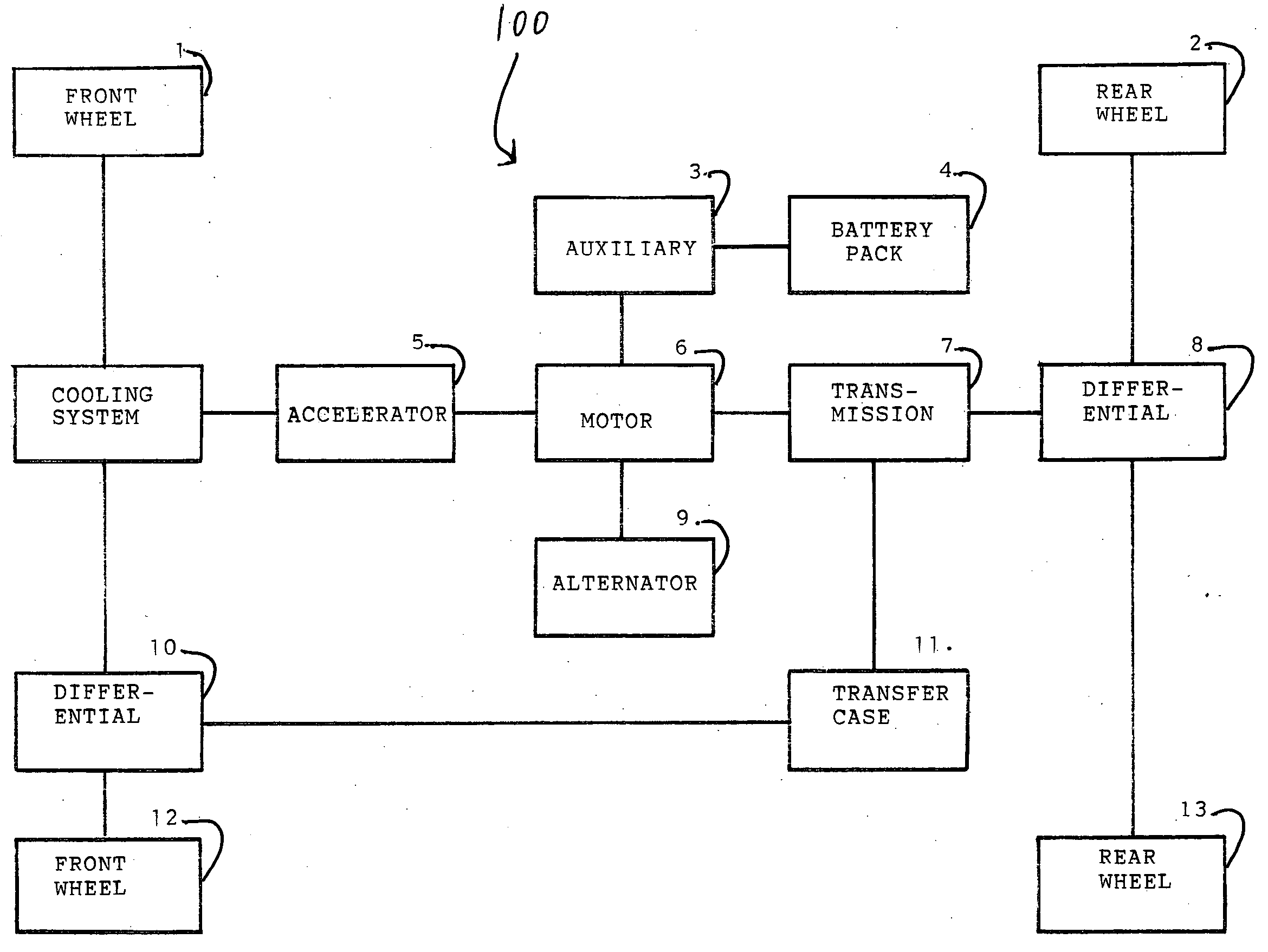
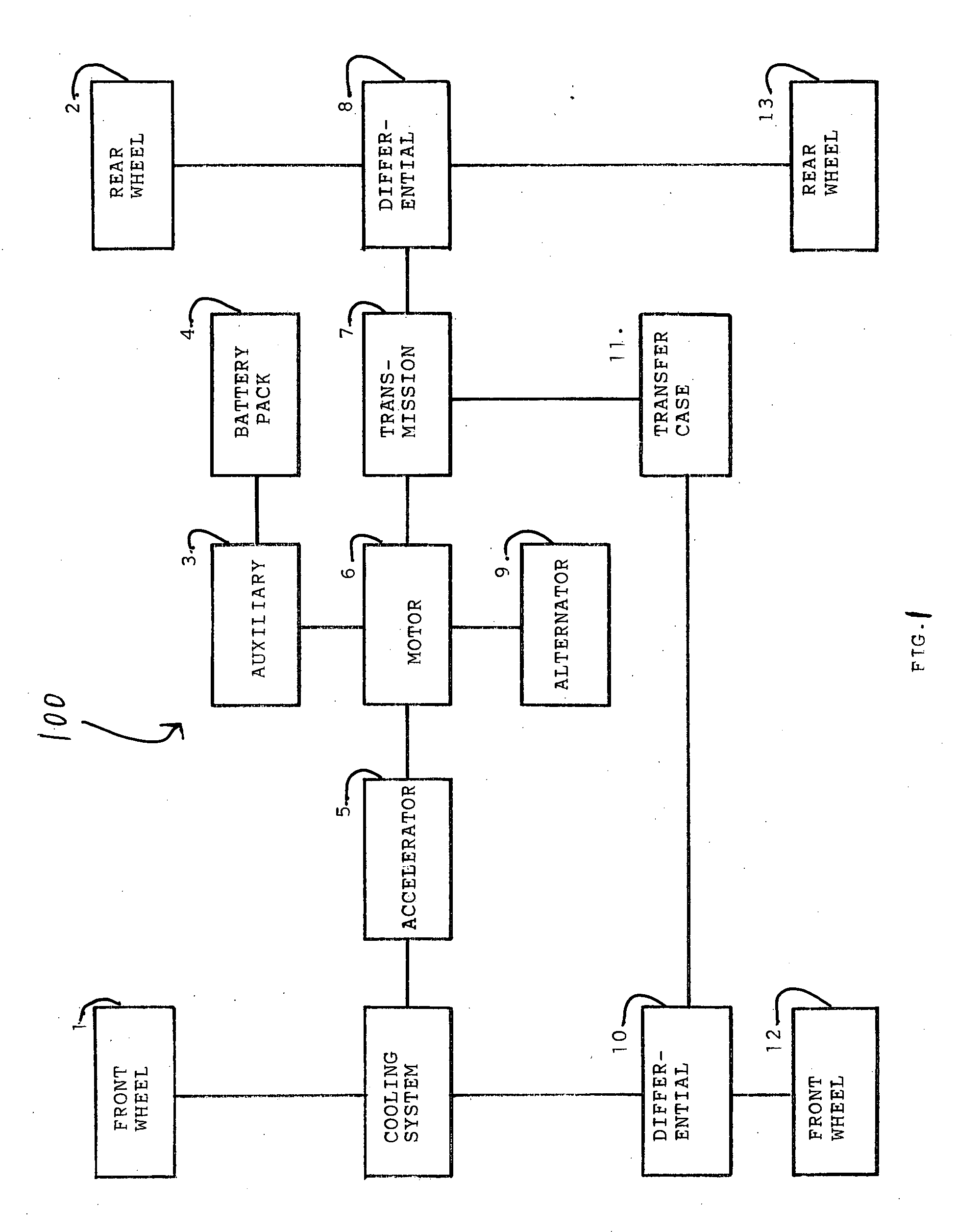
[0031] The apparatus of the present invention will now be illustrated by reference to the accompanying drawings. The electric vehicle of the present invention has been assigned reference numeral 100 Other elements have been assigned the reference numerals referred to below.

[0032] It is noted that the terms “electric motor” and “electric drive motor” is used herein to denote the vehicle's motor that causes the vehicle to move. Any other reference to a “motor” is to one or more motors that are designed merely to operate particular limited parts within the vehicle such as the motor for the fan, i.e. the fan motor, or the motors associated with the legs, i.e. the leg motors, as described in further detail below.

[0033] As seen from FIGS. 1-6, the electric vehicle of the present invention is an all-wheel drive electric vehicle that runs on a road and on an electrified track. Certain parts of the vehicle 100 are standard and well known. For example a chassis, a driving wheel and other we...


PUM


Abstract

A four wheel drive electric vehicle that runs on a road and on an electrified track comprising a motor, a battery pack, an accelerator, an alternator, an auxiliary generator capable, once the electric vehicle reaches approximately 20 m.p.h., of charging the battery when the battery pack is off or, when the battery pack is on, of transmitting electricity to the motor for extra power, an electrical system, a pair of motorized legs with balled feet, each of the motorized legs capable of being lowered so as to make contact with the electrified track that supplies electric power to drive the electric motor when the battery pack is off and a cooling system for cooling the motor including a cooling tank that contains oil that is circulated through oil piping. A separate portable charger for charging the batteries at home or when the vehicle is not in use is included.

Description

BACKGROUND OF THE INVENTION [0001] 1. Field of the Invention [0002] The field of this invention is electric vehicles, and more particularly, all-wheel drive electric vehicles. [0003] 2. Discussion of the Prior Art [0004] Electric vehicles are well known. However, one problem with known electric vehicles is that they typically can be driven only on a road. Although roads are the main way in which vehicles traverse land, and they have obvious advantages, roads also have disadvantages if the main vehicles that would be using them for travel are electric vehicles such as electric cars. One such disadvantage is that the electric vehicles have to be charged on the road constantly. That requires constant stopping which uses up time and the construction of electric stations for charging. Electric tracks have been proposed but a network of electric tracks has not been laid and even if such a network is laid it is unlikely that it would replace all existing roads in the foreseeable future. Th...

Claims


Application Information

Patent Timeline
Patent Type & Authority Applications(United States)
IPC IPC(8): B60K1/00B60K17/356
CPCB60K1/00Y02T90/127B60K2001/003B60L1/02B60L9/04B60L11/1816B60L2200/26B60L1/003B60L3/0061B60L11/1801B60L11/1811B60L11/1851B60L11/1877B60L2240/12B60L2240/36B60L2240/425B60L2250/28B60L2260/28Y02T10/7005Y02T10/705Y02T10/642Y02T90/14B60K17/356B60L50/53B60L50/66B60L53/14B60L53/20B60L58/10Y02T10/64Y02T10/70Y02T10/7072Y02T90/12
Inventor LANIER, THEODORE D.
Owner LANIER THEODORE D
Why Eureka
Try Eureka