
Door lock and operation mechanism

a door lock and operation mechanism technology, applied in the direction of process and machine control, anti-theft devices, program control, etc., can solve the problems of difficulty in opening the door, unfavorable installation in a general place, and substantially high pri

Inactive Publication Date: 2005-06-02
DENG SHENG BILL +1
View PDF25 Cites 66 Cited by
  • Summary
  • Abstract
  • Description
  • Claims
  • Application Information

AI Technical Summary

Problems solved by technology

That prior locking doorknob which recognizes the fingerprint has been applied to various kinds of doors using the above-mentioned function, however, when the prior locking doorknob has been used for an automobile door, the price is substantially high.
Furthermore, as mentioned above, the prior invention has been installed separately from a door and a controller so it is not conducive to be installed in a general place such as a house or an office.
In the case of manual doors, there is difficulty in opening the door because the detecting sensor is located separately from the doorknob.
This requires a two-step procedure to actually open the door, which can be cumbersome for the user.
The known systems are powered by some sort of battery located either in the door or the handle itself in which would necessarily need to be replaced upon depletion which is inefficient, often requires tools and a skilled locksmith, and can lead to failure of the door locking device at inopportune times.
The prior locking doorknob which recognizes a fingerprint has been applied to various kinds of doors using the above mentioned function, however, the prior locking doorknob which have been used are prohibitively expensive and, furthermore, the known handles have been located separately from a door and a controller so it is not conducive to be installed in a general place such as a house or an office.

Method used


Image

  • Door lock and operation mechanism
  • Door lock and operation mechanism
  • Door lock and operation mechanism

Examples


Embodiment Construction

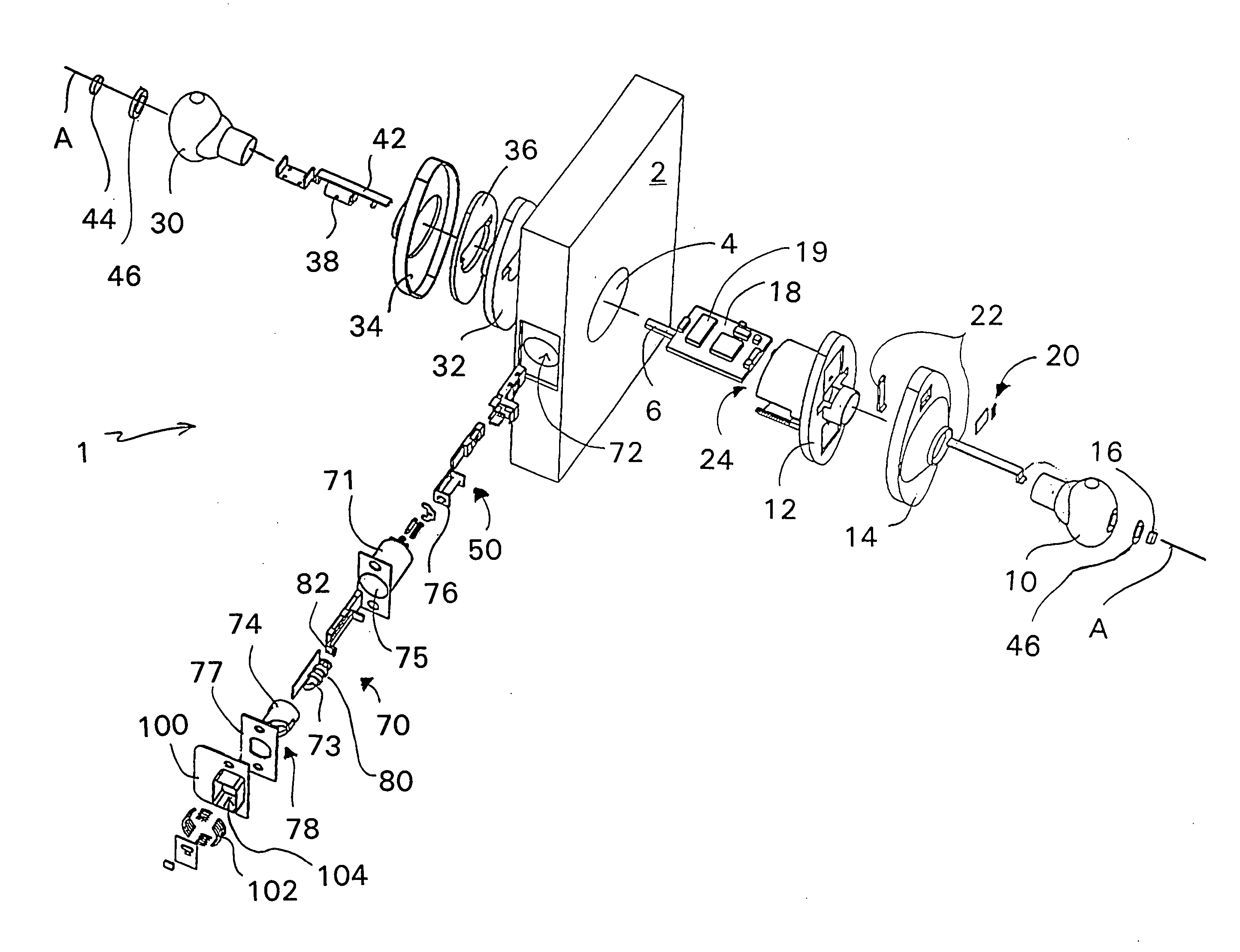
[0035] In general, and observing FIG. 1, the locking doorknob 1 or lever and operation system and mechanisms of the present invention will now be described. As an initial matter, the locking doorknob 1 consists of a first knob 10 or lever on one side of a door 2, and a second knob 30 or lever on a second opposing side of the door 2 as is typical and conventionally known for opening and closing a door. The first doorknob 10 or handle is connected with and supported in a doorknob hole 4 in the door 2 by a first doorknob body portion 12 and the second doorknob 30 or handle is also connected with and supported in the doorknob hole 4 in the door 2 by a respective second doorknob body portion 32. A respective first and second cover plates 14, 34 are interspaced between the respective handles and the body portions, and as is well known in the art, covers the exposed body portions on either side of the doorknob hole 4 mainly for purposes of aesthetics.

[0036] A knob operations shaft 6 which...


PUM


Abstract

A locking doorknob which recognizes a fingerprint, in which the detecting sensor of a fingerprint is installed on the spot of the doorknob that a thumb or other fingers are placed naturally as the door is being opened. The locking doorknob is an electromechanical device which can be powered by a remote electrical power system, specifically by electromagnetic induction through the door latch and strike plate. During operation, as soon as a user grasps the doorknob, a fingerprint is measured and searched and, if the fingerprint corresponds to a fingerprint previously input, the door is unlocked and the doorknob can be turned to open the door. An image capture device may also be combined with the doorknob to facilitate recognition of persons using or attempting to use the doorknob. In this way, fingerprint recognition, continuous real time security and opening of the door are performed at the same time.

Description

[0001] This application is a continuation-in-part of U.S. patent application Ser. No. 10 / 395,628 filed Mar. 21, 2003.FIELD OF THE INVENTION [0002] The present invention relates to a biometric locking doorknob or door lever which recognizes a fingerprint and which is installed for example on the door in a house, an apartment or an office. More particularly, the power dependent fingerprint detecting sensor in the doorknob or lever is supplied with the necessary electrical power for operation via a rechargeable battery which is charged via a remote recharging source circuit. According to the present invention, when an authorized person grasps the doorknob or lever, a command is issued to activate or deactivate the locking doorknob or lever accordingly when the persons fingerprint, as received by the fingerprint detecting sensor corresponds to a fingerprint previously input. BACKGROUND OF THE INVENTION [0003] Previously, a locking doorknob exists that includes a sensor plate which recog...

Claims


Application Information

Patent Timeline
Patent Type & Authority Applications(United States)
IPC IPC(8): E05B17/00E05B47/06G07C9/00
CPCE05B17/0083G07C9/00563E05B47/0676E05B47/0002Y10T292/37Y10T70/7062
Inventor DENG, SHENG BILLDENG, SHENG YUNG
Owner DENG SHENG BILL
Learn More