Omni-directional worklight

a worklight and omni-directional technology, applied in the field of portable worklights, can solve the problems of undesirable directional nature of worklights, and achieve the effect of high level of substantially omni-directional illumination

Active Publication Date: 2005-06-02
POLLUX LIGHTING
View PDF10 Cites 40 Cited by
  • Summary
  • Abstract
  • Description
  • Claims
  • Application Information

AI Technical Summary

Benefits of technology

[0004] The present invention provides a new form of portable worklight that can be energized to provide a high level of substantially omni-directional illumination. Briefly, the worklight includes an elongate lamp section including one or more lamp sockets for receiving one or more small fluorescent lamps such as compact fluorescent lamps of the screw-in variety. The lamp section includes a substantially transparent shield about the lamps and is structured and arranged to provide illumination substantially in a full circle ab...

Problems solved by technology

In some circumstances the direction...

Method used


Image

  • Omni-directional worklight
  • Omni-directional worklight
  • Omni-directional worklight

Examples


Embodiment Construction

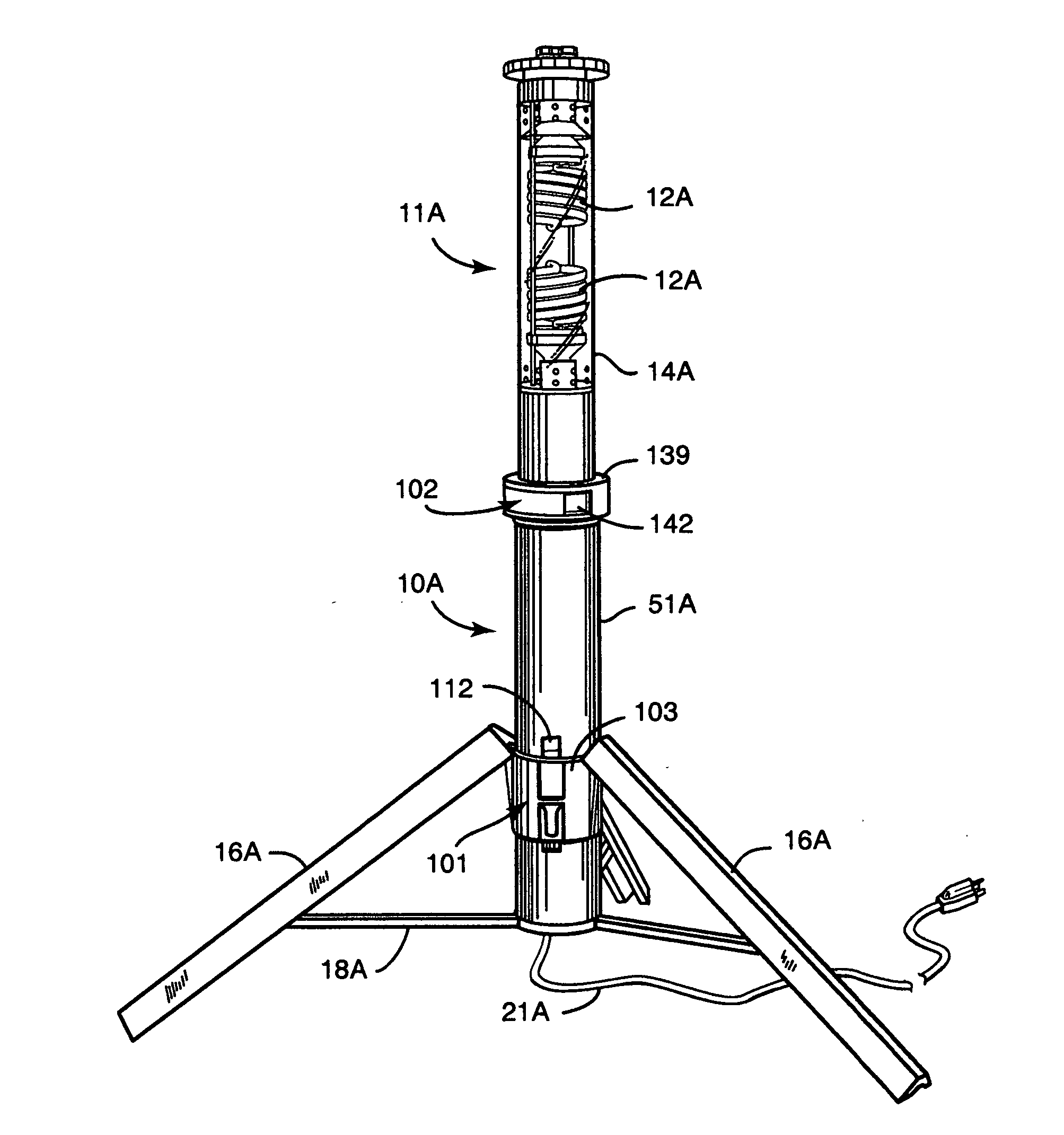
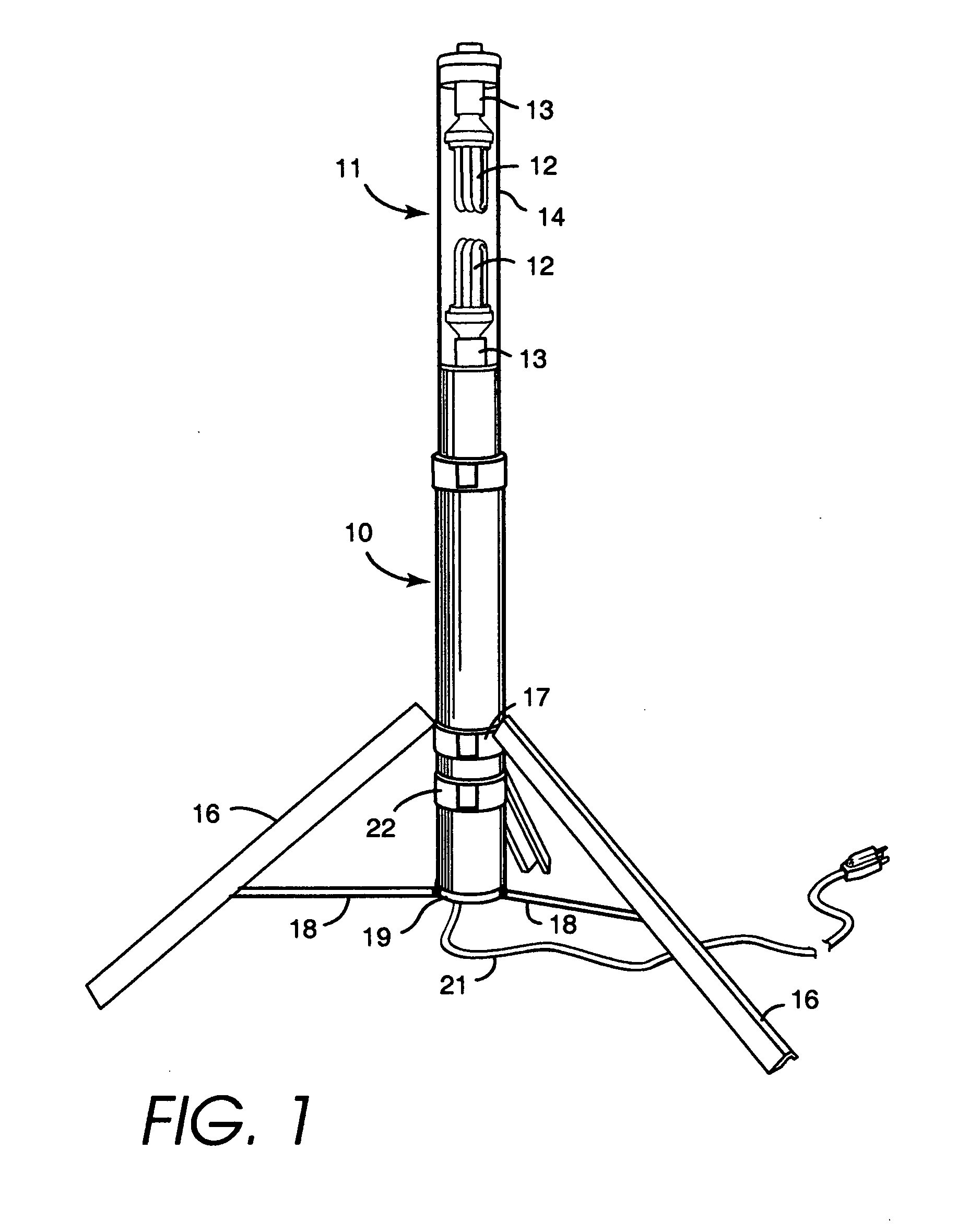
[0023]FIG. 1 shows an embodiment of a worklight according to the invention, which includes an elongate base section 10 and an elongate lamp section 11, which is formed and dimensioned to retract into the base section. The lamp section houses a pair of fluorescent light bulbs 12 of the screw-in variety that are received in sockets 13 disposed in the lamp section generally toward opposite ends of the lamp section so as to face one another. Lamp section 11 includes a shield member 14 substantially surrounding bulbs 12, which provides protection for the bulbs, yet permits the light to pass. In the embodiment shown here the member 14 is clear although it can also be diffusive to provide a softer light, reducing glare and at least partially obscuring the bulbs from view.

[0024] The worklight is preferably configured to use so-called compact fluorescent lamps. More generally, the worklight may be used with fluorescent lamps of the sort that have a self-contained ballast and are configured ...


PUM


Abstract

A portable worklight providing a high level of substantially omni-directional illumination. Briefly, the worklight includes an elongate lamp section including one or more lamp sockets for receiving one or more small fluorescent lamps such as compact fluorescent lamps of the screw-in variety. The lamp section includes a substantially transparent shield about the lamps and is structured and arranged to provide illumination substantially in a full circle about the lamp section. The lamp section is retractable into an elongate base section that is shaped and structured to receive the lamp section snugly in its interior. In the retracted configuration the worklight forms a compact unit for carrying, transporting and storing the worklight. The worklight may also include legs that may be retracted along the base section and deployed for supporting the worklight during use.

Description

BACKGROUND OF THE INVENTION [0001] The present invention relates to portable worklights providing wide area lighting. [0002] Portable worklights are well known for use on construction sites, in automotive shops, for do-it-yourself projects around the home and for many other uses. The worklights typically take the form of one or more worklight heads mounted on a base, which may form a stand for setting the worklight on the ground or work surface and which may additionally or alternatively be formed for mounting on a tripod. The worklight heads are generally directional in that they illuminate a confined area lying in a particular direction. In some models the heads are designed to provide a wide area of illumination extending, say, in the forward direction; in other models the illumination may be more focused. In recent years worklights using halogen lamps as the light source have been popular because these lamps are extremely bright. More recently, fluorescent lamps have been used i...

Claims


Application Information

Patent Timeline
IPC IPC(8): F21L14/00F21V17/00F21V21/06F21V21/14F21V21/22F21V21/40F21V23/04
CPCF21L14/00F21V17/007F21W2131/1005F21V21/22F21V23/04F21V21/06F21Y2113/00F21Y2103/30F21Y2103/37
Inventor LEE, WADESANDELL, DONALD R.
Owner POLLUX LIGHTING
Why Eureka
Try Eureka