
Open socket

Inactive Publication Date: 2005-06-02
SAMSUNG ELECTRONICS CO LTD
View PDF4 Cites 1 Cited by
  • Summary
  • Abstract
  • Description
  • Claims
  • Application Information

AI Technical Summary

Benefits of technology

[0010] At least one embodiment of the present invention provides an open socket in which the lower portion of the open socket is entirely or partially opened, thereby minimizing an influence on a module and the open socket of foreign substances that enter the open socket.
[0011] At least one embodiment of the present invention provides an open socket in which an electrical connection member of the open socket that contacts an electrical connection member of a module has a continuously convex insertion profile to reduce, if not minimize, a contact area therebetween, which reduces the possibility of foreign substances being generated when the electrical connection members of the open socket and the module contact each other.

Problems solved by technology

For several reasons, foreign substances that enter the socket have a negative influence upon the electrical connection members of the socket and module, potentially resulting in an electrical contact failure.
As a result, test results can become unreliable and users may complain about modules if the modules with foreign substances are released into the market.
In particular, if the modules include rigid foreign substances, the modules and sockets into which they are inserted may get broken, resulting in defects in products or productivity deterioration.

Method used


Image

  • Open socket
  • Open socket
  • Open socket

Examples


first embodiment

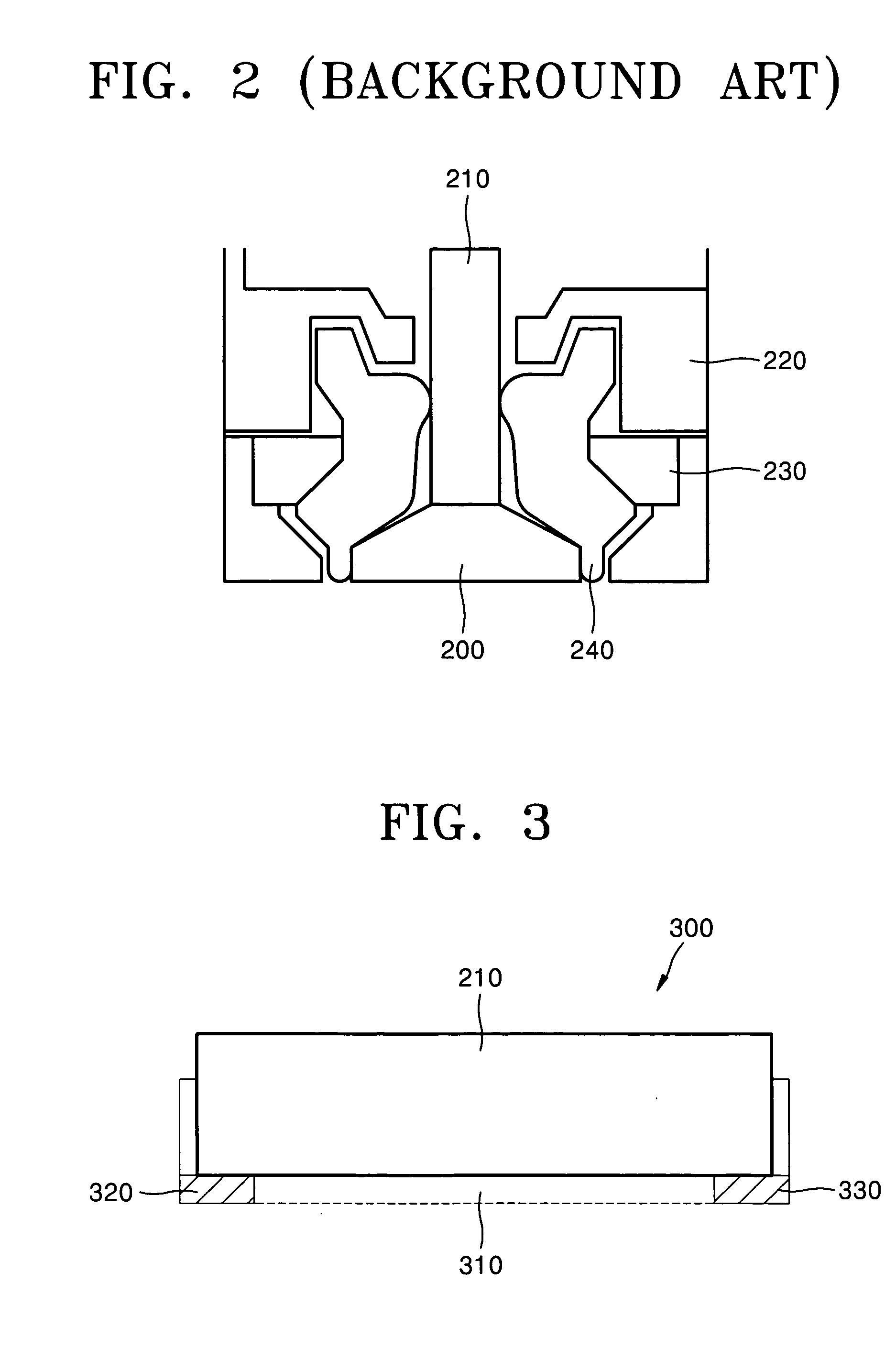
[0023]FIG. 3 is a longitudinal sectional view of an open socket 300 according to at least the present invention.

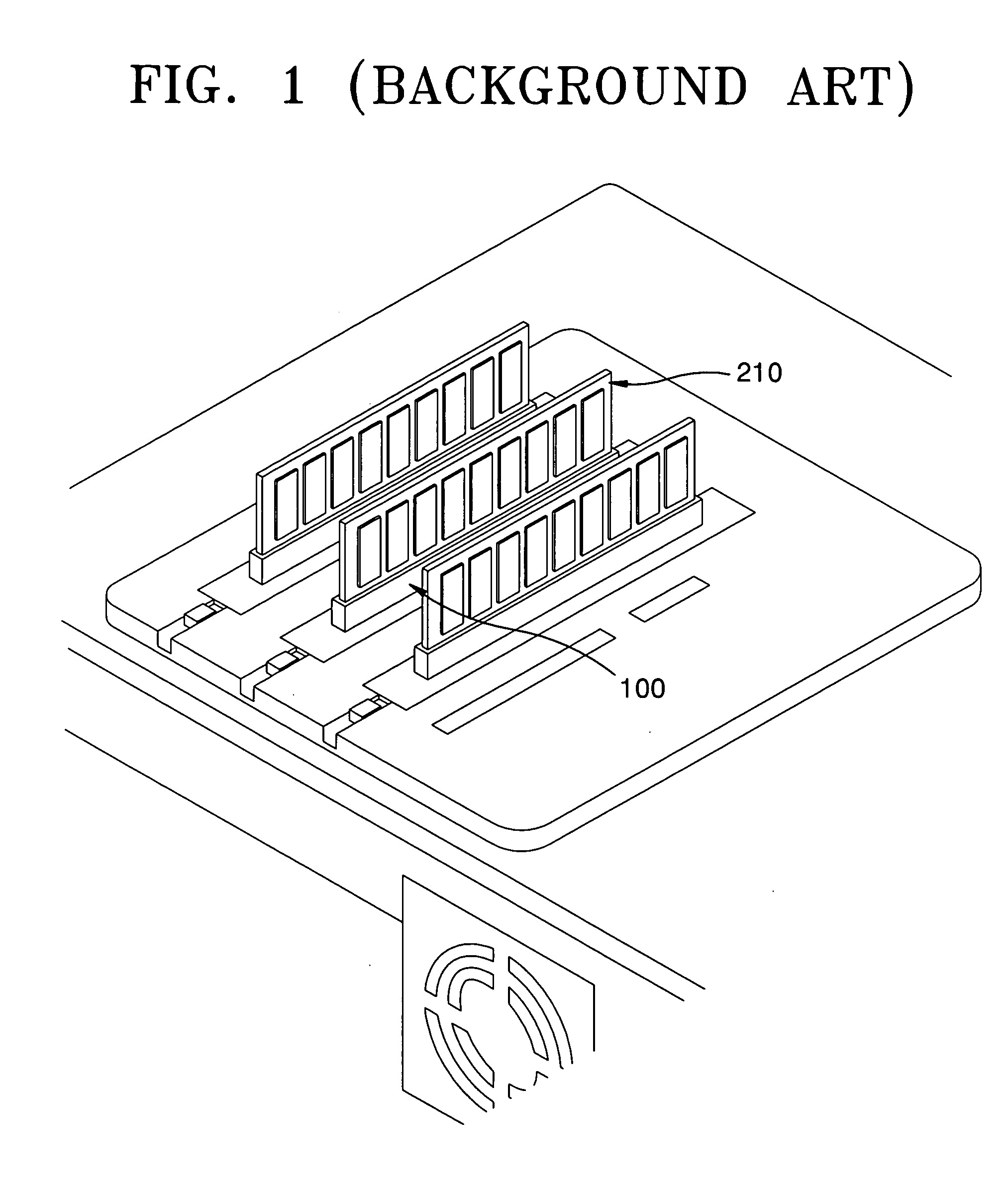
[0024] Referring to FIG. 3, the open socket 300 is different from the Background Art socket 100 of FIG. 1, e.g., by including: two lower supports 320 and 330 instead of one larger support according to the Background Art. Lower supports 320 and 330 support the ends of the lower portion of a module 210 when it is inserted into the open socket 300. A center opening (or gap) 310 (indicated by a dotted line) corresponds to what otherwise would have been a solid center section of the larger Background Art lower support. The gap 300 leaves a center region of the lower portion of the module 210 unsupported and also provides a passage through which foreign substances can exit the open socket 300.

[0025]FIG. 4 is a transverse sectional view of the edges 320 and 330 of the open socket 300 of FIG. 3.

[0026]FIG. 5 is a transverse sectional view of the center portion 310 of the open soc...

second embodiment

[0029] An open socket 300 according to at least the present invention is indicated in FIG. 3 via the stippled portions of the lower supports 320 and 330, which would not be provided such that no part of the supports 320 and 330 would be located under a module that is inserted into the open socket 300. In this embodiment, another structure should be included to support the module. Alternatively, only one of the stippled portions, e.g., that of lower support 330 is omitted such that only lower support 320 limits the depth of insertion of the module 210.

third embodiment

[0030]FIG. 6 is a transverse sectional view of an open socket 600 according to at least the present invention.

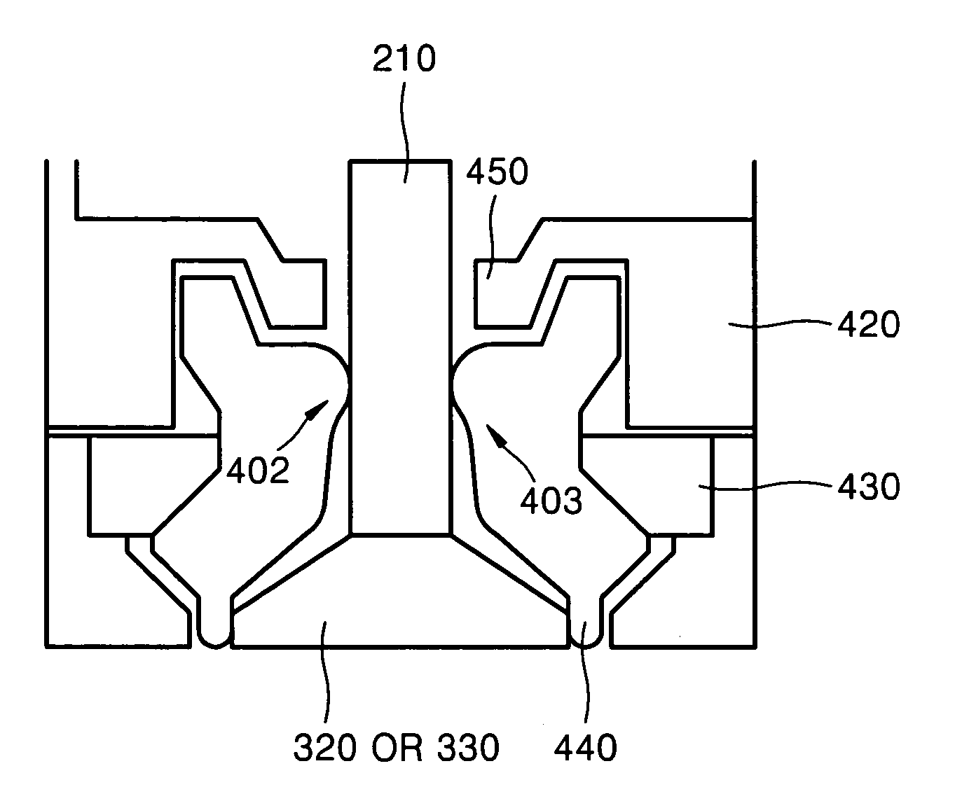
[0031] Referring to FIG. 6, an open socket 600 includes a pin 600 whose electrical connection member 602 has an arcuate, e.g., round, shape to provide a different (e.g., relative to the electrical connection member 402) and reduced contact area 610 between the electrical connection member 602 of the open socket 600 and an electrical connection member 602 of the module 600, thereby reducing a possibility of generation of foreign substances in spite of repetitive contact between the electrical connection member 600 and the electrical connection member 610. In addition, a portion of the electrical connection member 602 that makes contact with the module 210 is located relatively farther from a flange 450 then the corresponding contact portion of the electrical connection member 402.

[0032] A surface of the electrical connection member 602 between an upper point 612 and a lower ...


PUM


Abstract

An open socket, into which a module can be inserted, may include: a body into which the module is insertable; a pin to contact an electrical connection member of the inserted module, the pin serving as at least a part of an electrical signal path to / from the module upon insertion thereof; an elastic biasing member to exert an elastic biasing force to cause the pin to contact the module; and at least one lower support to limit insertion depth as being a depth at which a lower portion of the inserted module comes to rest upon the at least one lower support; the body and the at least one lower support being constructed and arranged to provide a gap adjacent the at least one support, which leaves an area of the socket underlying the lower portion of the inserted module open to the outside.

Description

CROSS REFERENCE TO RELATED APPLICATION [0001] This application claims the priority of Korean Patent Application No. 2003-85818, filed on Nov. 28, 2003, in the Korean Intellectual Property Office, the disclosure of which is hereby incorporated by reference in its entirety. BACKGROUND OF THE INVENTION [0002]FIG. 1 is a perspective view of a conventional socket 100 and a module 210 inserted into the socket, according to the Background Art. [0003] It can be seen from FIG. 1 that the module 210 should be inserted into the fixed socket 100 to test electrical characteristics of the module 210. [0004]FIG. 2 is a transverse-sectional view of the socket 100 of FIG. 1. [0005] Referring to FIG. 2, the socket 100 includes a body 220, a synthetic rubber biasing member 230, a pin 240, and a lower support 200. [0006] The body 220 retains the external shape of the socket 100 and supports the inserted module 210. After the module 210 is inserted into the socket 100, the pin 240 contacts an electrical...

Claims


Application Information

Patent Timeline
IPC IPC(8): H01R13/24H01R33/76H01R24/00
CPCH01R23/70H01R13/2471H01R13/111H01R33/76
Inventor LEE, DONG-CHUNKIM, BYUNG-MANYU, KWANG-SUSHIN, DONG-WOOLEE, YOUNG-SOO
Owner SAMSUNG ELECTRONICS CO LTD
Features
  • Generate Ideas
  • Intellectual Property
  • Life Sciences
  • Materials
  • Tech Scout
  • Unparalleled Data Quality
  • Higher Quality Content
  • 60% Fewer Hallucinations
Learn More