Female terminal for heavy current and female terminal for heavy current with shell

a terminal and terminal technology, applied in the field of female terminals, can solve the problems of insufficient reduction of contact resistance and small contact area between projections and pins, and achieve the effects of high contact pressure, large contact area, and high contact pressur

Active Publication Date: 2005-06-02
JST MFG CO LTD
View PDF2 Cites 16 Cited by
  • Summary
  • Abstract
  • Description
  • Claims
  • Application Information

AI Technical Summary

Benefits of technology

[0006] The female terminal for heavy current of Japanese Patent Unexamined Publication Heisei 10-116644 provides stable contact resistance, but as the projections make point contact with the pin of the male terminal, the contact area between the projections and the pin is small and the contact resistance can not be reduced sufficiently.

Problems solved by technology

The female terminal for heavy current of Japanese Patent Unexamined Publication Heisei 10-116644 provides stable contact resistance, but as the projections make point contact with the pin of the male terminal, the contact area between the projections and the pin is small and the contact resistance can not be reduced sufficiently.

Method used


Image

  • Female terminal for heavy current and female terminal for heavy current with shell
  • Female terminal for heavy current and female terminal for heavy current with shell
  • Female terminal for heavy current and female terminal for heavy current with shell

Examples


Embodiment Construction

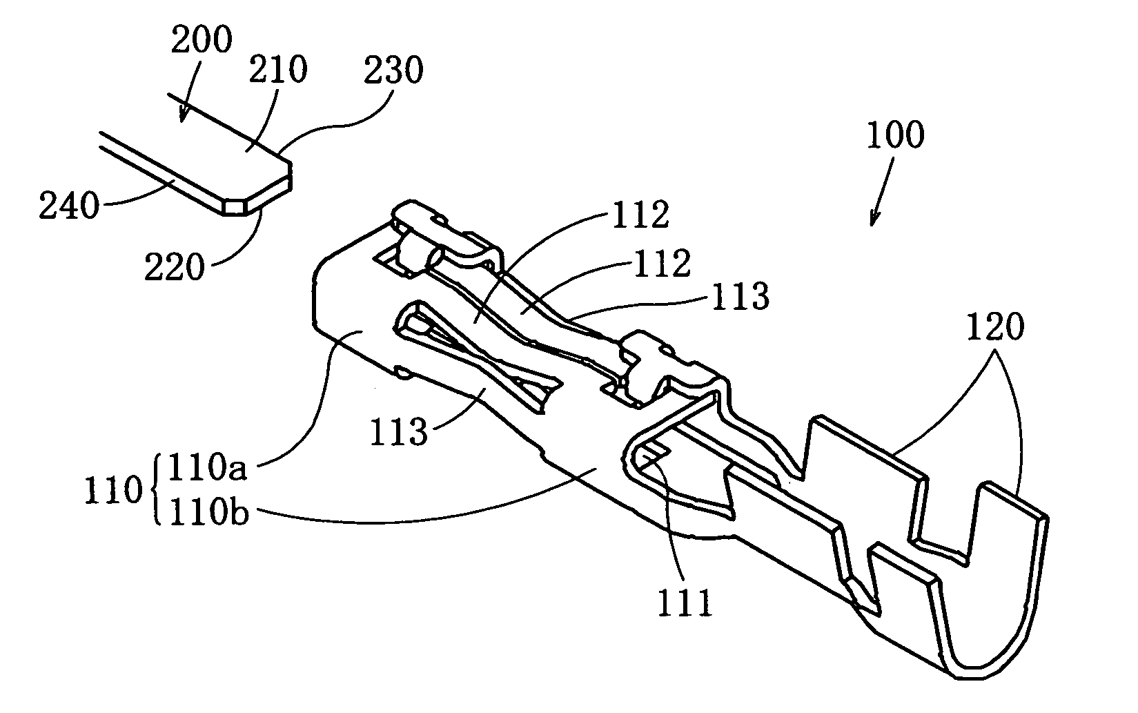
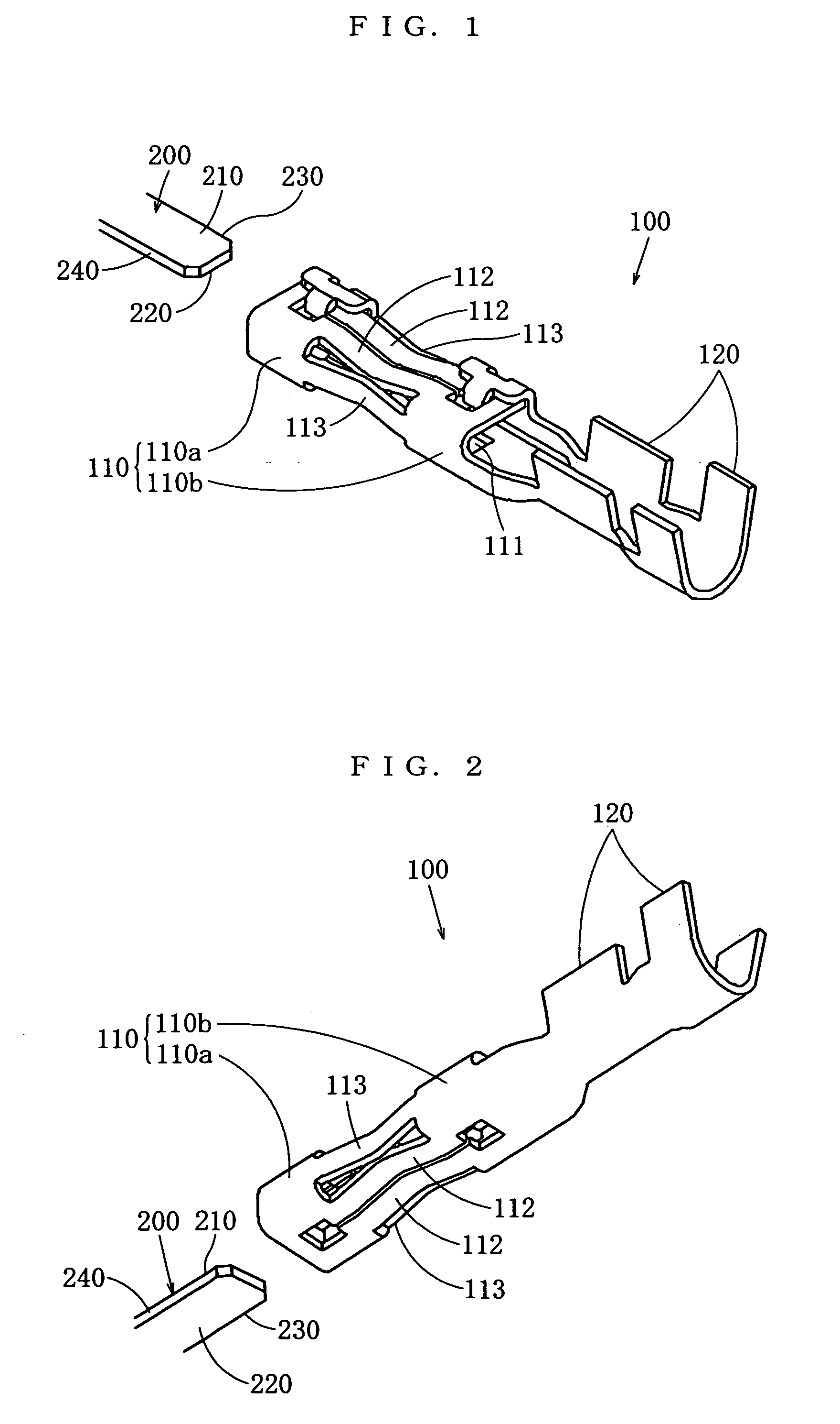
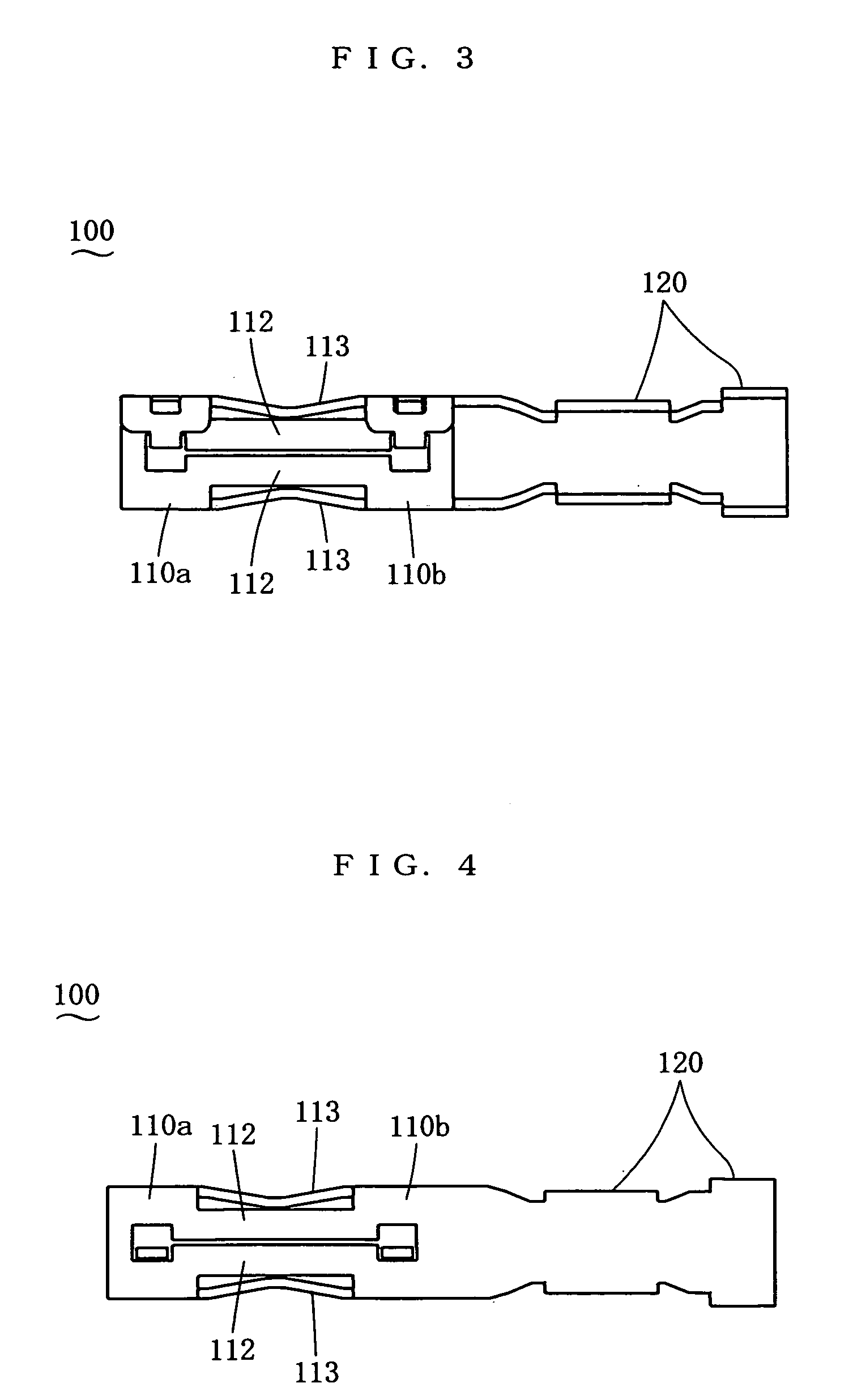
[0056] In the following, some embodiments of the present invention will be described. FIG. 1 through FIG. 12 show the female terminal for heavy current 100 of the first embodiment of the present invention. A depth direction, a width direction and a height direction all being perpendicular to each other are assumed, and these directions are used for the description. In the case of this embodiment, with reference to FIG. 3, the left-right direction of the diagram is the depth direction, the left of the diagram is the rear in the depth direction, and the right is the front in the depth direction. The direction perpendicular to the plane of the paper of the diagram is the height direction, and the top-bottom direction of the diagram is the width direction.

[0057] As shown in FIG. 1, a blade 200 of a blade-type male terminal (its body is not illustrated) is inserted into and withdrawn from this female terminal for heavy current 100. This blade 200 is formed into a substantially plate for...


PUM


Abstract

To provide a female terminal for heavy current, which reduces the contact resistance between it and a male terminal, allows stable flow of heavy current at low loss and correctly positions a blade. The body part of the female terminal for heavy current is provided with a first elastic piece, which is provided at least on one side in the height direction of a receiving space in such a way that it can undergo elastic deformation in the height direction and has, on the inner side thereof, a contacting part extending for a certain width, and a second elastic piece, which is provided at least on one side in the width direction of the receiving space in such a way that it can undergo elastic deformation in the width direction and has, on the inner side thereof, a contacting part extending for a certain height. When the blade is inserted into the receiving space, the contacting part of the first elastic piece will contact, with a contact pressure, one end face in the height direction of the blade and the contacting part of the second elastic piece will contact, with a contact pressure, one end face in the width direction of the blade.

Description

BACKGROUND OF THE INVENTION [0001] 1. Field of the Invention [0002] The present invention belongs to the field of female terminals, and relates to a female terminal for heavy current into which and from which a blade of a blade-type male terminal having a substantially plate-shaped blade is inserted and withdrawn. [0003] 2. Related Art [0004] Japanese Patent Unexamined Publication Heisei 10-116644 discloses a female terminal for heavy current having a tubular contacting part for a terminal pin of a male terminal to be inserted, wherein a ring-shaped thin wall part is provided on the outer circumference on the terminal pin insertion end side of said tubular contacting part, said thin wall part being provided with a plurality of projections projecting from the inner face of the tubular contacting part at appropriate intervals. [0005] Japanese Patent Unexamined Publication Heisei 11-67310 discloses a terminal for heavy current charging, comprising a female terminal having an insertion ...

Claims


Application Information

Patent Timeline
Patent Type & Authority Applications(United States)
IPC IPC(8): H01R13/11H01R13/115H01R13/187
CPCH01R13/187H01R13/113
Inventor CHEN, PING
Owner JST MFG CO LTD
Why Eureka
Try Eureka