Power and timing control methods and apparatus

Inactive Publication Date: 2005-06-02
QUALCOMM INC
View PDF12 Cites 109 Cited by
  • Summary
  • Abstract
  • Description
  • Claims
  • Application Information

AI Technical Summary

Benefits of technology

[0020] During the on state, the base station and mobile node exchange timing control signals using one or more dedicated control channels allowing the mobile node to periodically adjust its transmission timing, e.g., symbol timing, to take into consideration changes in distance and other factors which might cause the transmitted signals to drift timing from the base station's perspective, with the signals transmitted by other mobile nodes. As discussed above, the use of timing control signaling and performing timing control signaling operations, such as updating transmission timing, is important in many systems which use orthogonal frequency division multiple access in the uplink to avoid interference from transmission signals generated by multiple nodes in the same cell.
[0023] Maintaining timing control while in the hold-state allows the mobile nodes to transmit their uplink requests without generating interference to other mobiles within the same cell and having a dedicated uplink control resource ensures that the delays for state transition are minimal as the requests for state transitions do not collide with similar requests from other mobile nodes as may occur in the case of shared uplink resources. Since timing control signaling is maintained, when the mobile node transitions from the hold state to the on state it can transmit data without much delay, e.g., as soon as the requested uplink resource is granted, without concerns about creating interference for other mobile nodes in the cell due to drift of uplink symbol timing. During the hold state, transmission power control signaling may be discontinued or performed less frequently, e.g., at greater intervals than performed during on state operation. In this manner, the dedicated control resources used for power control signaling can be eliminated or reduced allowing fewer resources to be dedicated to this purpose than would be possible if power control signaling for all nodes in the hold state was performed at the same rate as in the on state.
[0033] To further reduce power consumption in the mobile node associated with monitoring for control signals, in accordance with one feature of the invention control channels monitored during the hold and sleep states are implemented as periodic control channels. That is, signals are not broadcast on a continuous basis on the control channels monitored in the hold and sleep states. Thus, during the hold and sleep states the mobiles monitor for control signals at periodic intervals and save power by not monitoring for control signals at those times when control signals are not transmitted on the monitored channels. To further decrease the time a particular mobile needs to monitor for control signals during the hold and sleep states, portions, e.g., segments, of the periodic control channels may be dedicated to one or a group of mobile nodes. The mobile nodes are made aware of which control channel segments are dedicated to them and then monitor the dedicated segments as opposed to all the segments in the control channels. This allows monitoring for control signals to be performed in the hold and sleep states by individual mobile nodes at greater periodic intervals than would be possible if the mobile were required to monitor all segments of the periodic control channels.
[0038] Unlike some other known systems, a wireless terminal implemented in accordance with the invention may remain in a hold or sleep state for extended periods of time, e.g., many milliseconds, e.g., 10 or more milliseconds, without transmitting any signals. This offers significant power advantages over other systems where timing and / or power control signaling rates must be maintained at far more frequent intervals.

Problems solved by technology

In the case of a shared communications channel conflicts may result when multiple nodes, at the same time attempt to transmit a control signal using the shared communications channel.

Method used


Image

  • Power and timing control methods and apparatus
  • Power and timing control methods and apparatus
  • Power and timing control methods and apparatus

Examples


Embodiment Construction

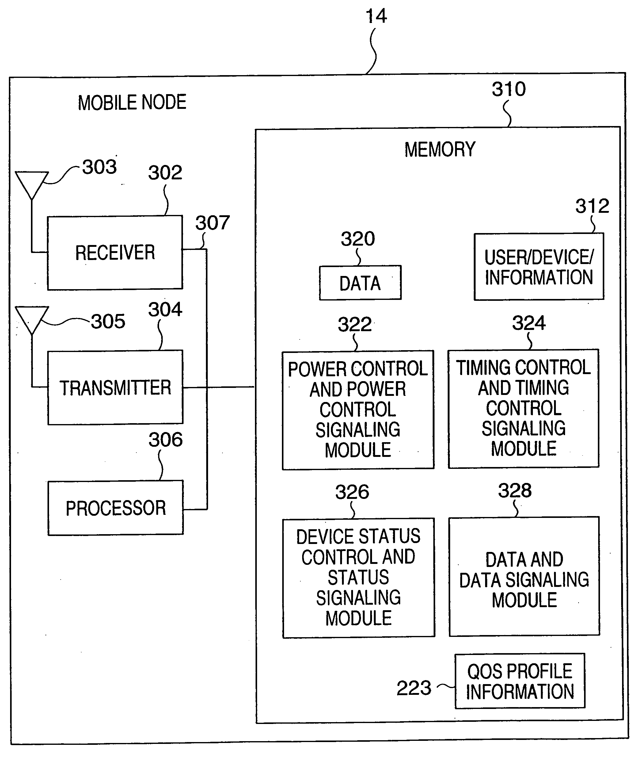
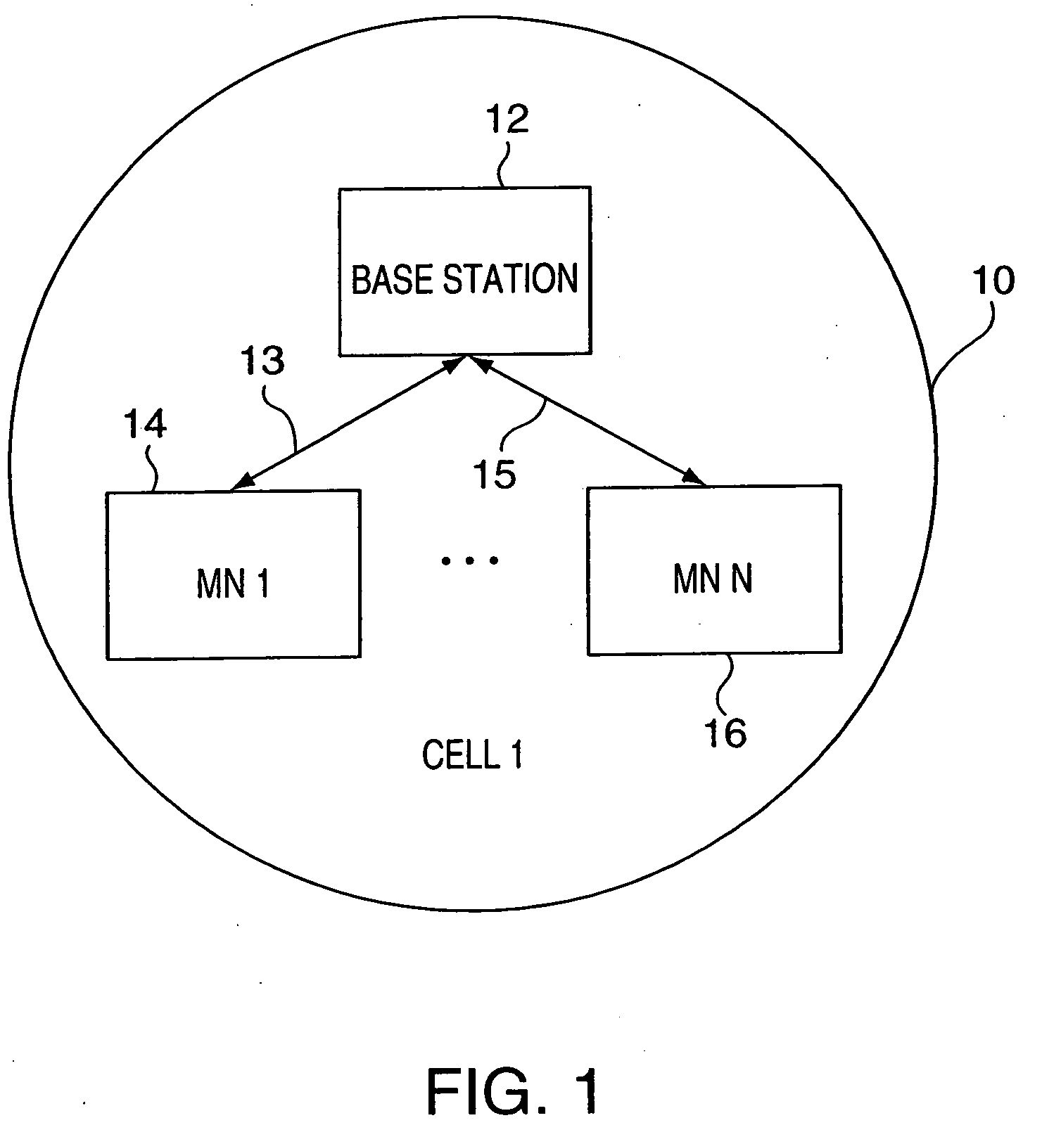
[0053]FIG. 1 illustrates a communications cell 10 implemented in accordance with the present invention. A communications system may include multiple cells of the type illustrated in FIG. 1. The communications cell 10 includes a base station 12 and a plurality, e.g., a number N, of mobile nodes 14, 16 which exchange data and signals with the base station 12 over the air as represented by arrows 13, 15. In accordance with the invention, the base station 12 and mobile nodes 14, 16 are capable of performing and / or maintaining control signaling independently of data signaling, e.g., voice or other payload information, being communicated. Examples of control signaling include power control, downlink channel quality reports, and timing control signaling.

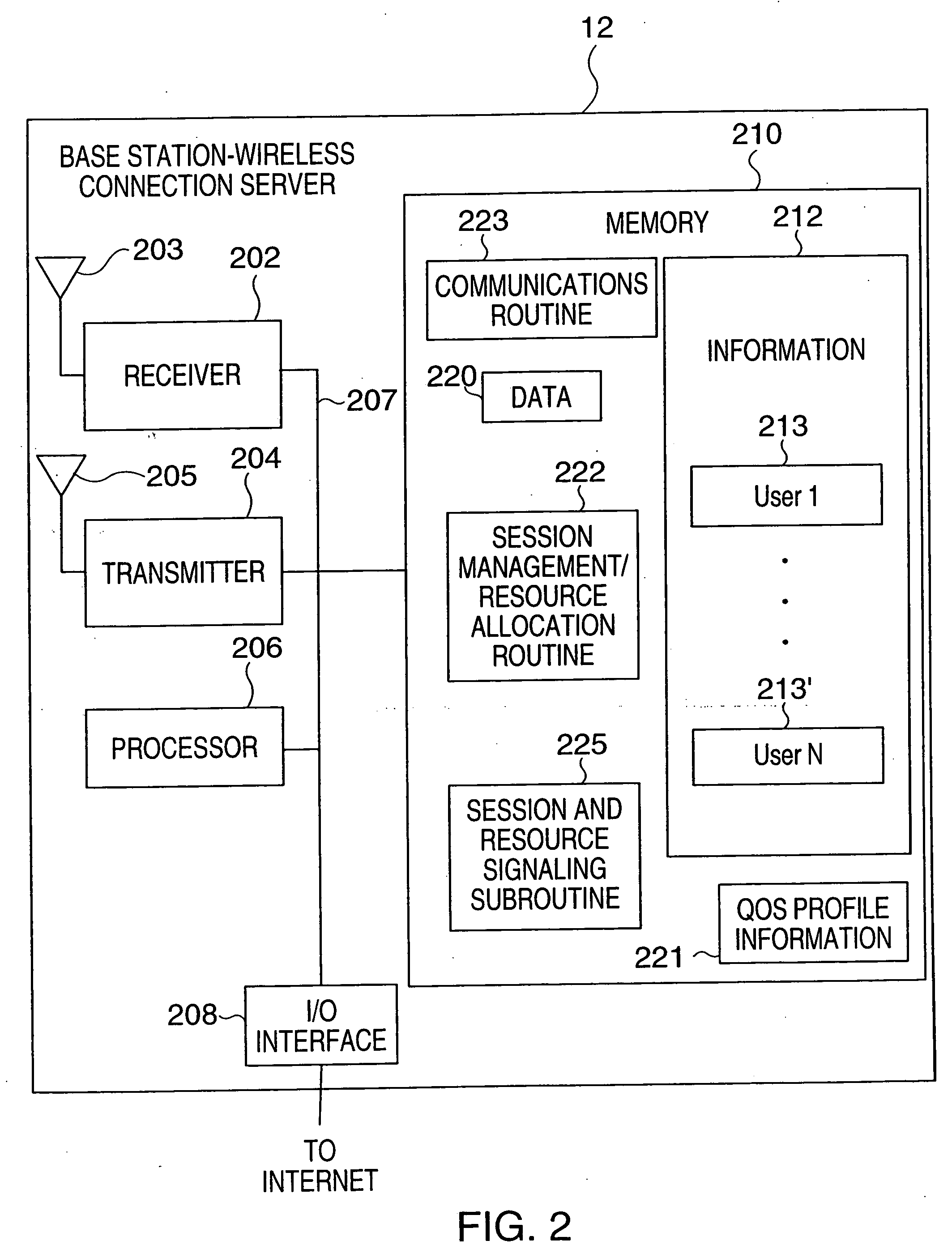
[0054]FIG. 2 illustrates a base station implemented in accordance with the present invention. As shown, the exemplary BS 12 includes a receiver circuit 202, transmitter circuit 204, processor 206, memory 210 and a network interface 208 cou...


PUM


Abstract

The use of multiple states of mobile communication device operation to allow a single base station to support a relatively large number of mobile nodes is described. The various states require different amounts of communications resources, e.g., bandwidth. Four supported states of operation are an on-state, a hold-state, a sleep-state, and an access-state. Each mobile node in the on-state is allocated communication resources to perform transmission power control signaling, transmission timing control signaling and to transmit data as part of a data uplink communications operation. Each mobile node in the hold-state is allocated communication resources to perform transmission timing control signaling and is provided a dedicated uplink for requesting a state transition and a shared resource for transmitting acknowledgements. In the sleep state a mobile node is allocated minimal resources and does not conduct power control signaling or timing control signaling. Data may be received in the on and hold states.

Description

RELATED APPLICATION [0001] This application is a continuation application of U.S. patent application Ser. No.10 / 636,482 filed Aug. 7, 2003 which claims the benefit of U.S. Provisional Patent Application Ser. No. 60 / 401,920 filed on Aug. 8, 2002 and which is a continuation-in-part application of issued U.S. patent application Ser. No. 10 / 324,194 filed Dec. 20, 2002, which issued as U.S. Pat. No. 6,788,963 and which is also a continuation-in-part application of U.S. patent application Ser. No. 10 / 378,563 filed Mar. 3, 2003; this application is also a continuation-in-part application of International Application No. PCT / US03 / 24889, filed Aug. 7, 2003 which designated the U.S., the entire content of each of the preceding identified patent applications is hereby expressly incorporated by reference.FIELD OF THE INVENTION [0002] The present invention is directed to wireless communications systems and, more particularly, to methods and apparatus for supporting a plurality of mobile nodes in...

Claims


Application Information

Patent Timeline
Patent Type & Authority Applications(United States)
IPC IPC(8): H04B7/005H04W76/04H04L12/56H04M1/73H04W24/00H04W28/04H04W52/02H04W52/08H04W52/28H04W52/60H04W68/02H04W72/00H04W72/12
CPCH04W16/12H04W72/048H04W24/00H04W36/06H04W52/0235H04W52/028H04W52/08H04W52/281H04W52/283H04W52/286H04W52/287H04W52/288H04W52/60H04W68/02H04W68/025H04W72/00H04W72/0413H04W16/14Y02D30/70H04W72/51H04W72/21
Inventor LAROIA, RAJIVLI, JUNYIUPPALA, SATHYADEV VENKATA
Owner QUALCOMM INC
Why Eureka
Try Eureka