Instrumentation for insertion of an inter-vertebral prosthesis

Active Publication Date: 2005-06-02
DEPUY SPINE INC (US)
View PDF11 Cites 156 Cited by
  • Summary
  • Abstract
  • Description
  • Claims
  • Application Information

AI Technical Summary

Benefits of technology

[0010] In another embodiment of the invention, an actuating device is provided which comprises an actuating lever which is mounted at its front end on the instrument body or the first prosthesis holder so as to pivot. The pivot axis extends transversely with respect to the longitudinal direction of the instrument body and to the direction of spreading. Behind this axis, the lever has a limit stop which acts directly or indirectly on the second prosthesis holder. At the rear end, the lever is designed such that it can be operated by hand. In the unspread state of the instrument, the lever is at a certain angular distance from the instrument body. If it is pulled by hand, or by suitable aids such as a threaded spindle, toward the instrument body, the limit stop moves the second prosthesis holder away from the first prosthesis h

Problems solved by technology

Nevertheless, the introduction of

Method used


Image

  • Instrumentation for insertion of an inter-vertebral prosthesis
  • Instrumentation for insertion of an inter-vertebral prosthesis
  • Instrumentation for insertion of an inter-vertebral prosthesis

Examples


Embodiment Construction

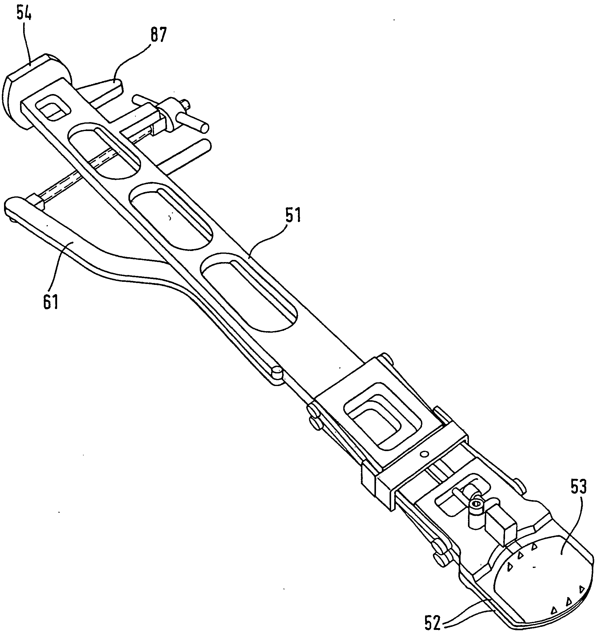
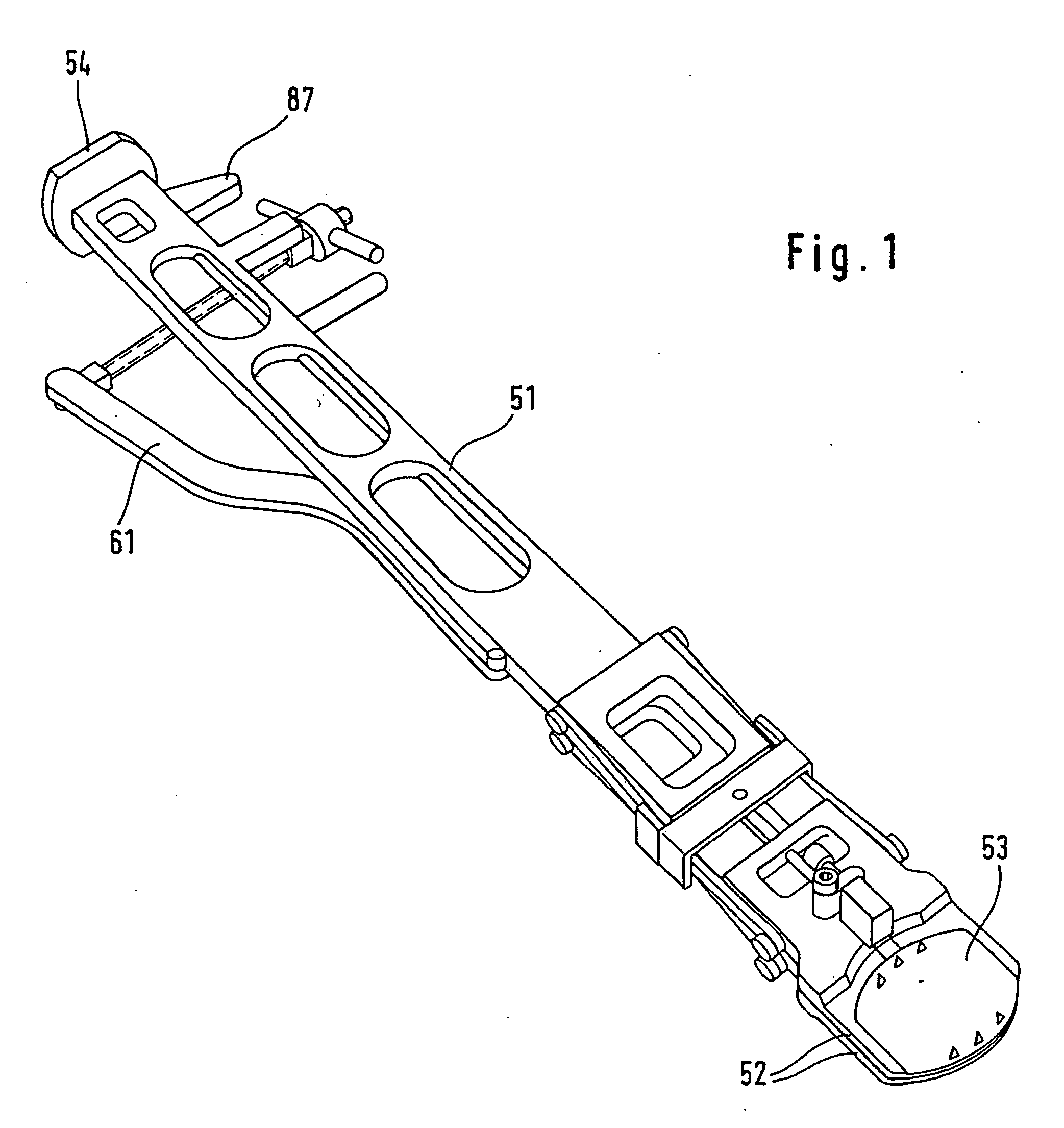
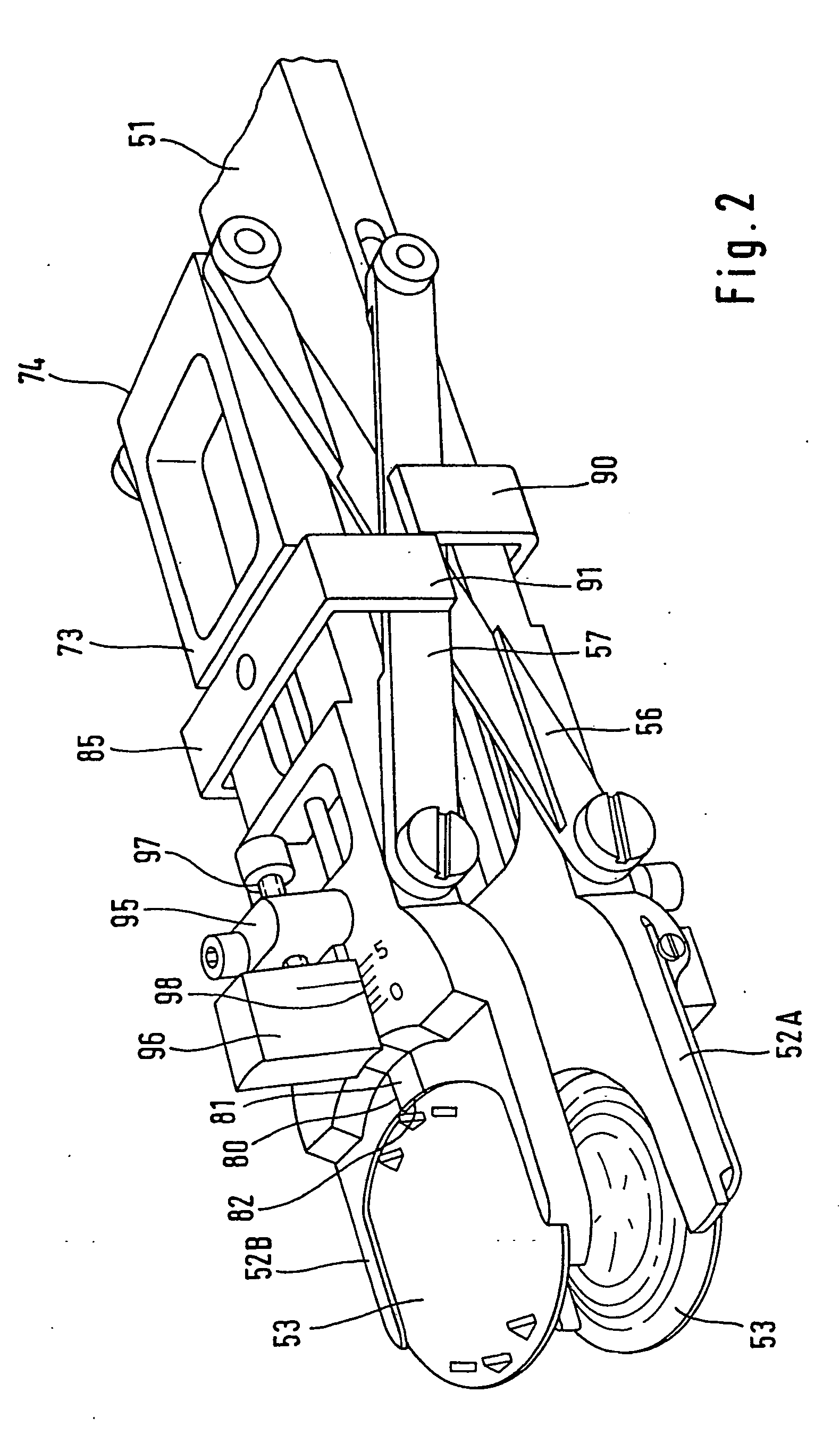
[0022] At the front end of the instrument body 51 there are two holders 52 for prosthesis plates 53. The prosthesis holders 52 are fork-shaped and open at the end. Their side branches form guides for the edge of the prosthesis plates 53. Their direction coincides with the longitudinal direction of the instrument body. They allow the prosthesis plates to overcome a frictional force and be inserted easily into the prosthesis holders 52, and removed therefrom, in the longitudinal direction of the instrument. At the rear end, the prosthesis body 51 has a strike plate 54. By striking this plate, the prosthesis plates 53 held by the prosthesis holders 52 can be driven in between two vertebral bodies.

[0023] The lower prosthesis holder 52A (FIGS. 9 and 10) is fixedly connected to the instrument body 51, and in the example illustrated is even made integral therewith. The upper prosthesis holder 52B is connected to the instrument body 51 via a scissor arrangement consisting of scissor member...


PUM


Abstract

An instrument for inserting an intervertebral prosthesis, comprising two prosthesis holders which are connected by a parellel guide and can be spread apart from one another and are intended to receive a pair of prosthesis plates. The first prosthesis holder is arranged fixedly on an elongate instrument body. The second prosthesis holder is held from the instrument body by means of a parallel guide. The parts connecting the second prosthesis holder to the instrument body or to the first prosthesis holder delimit on both sides a central through-opening which extends like a channel in the longitudinal direction of the instrument body and whose width corresponds at least to the transverse dimensions of a prosthesis core, to be inserted between the prosthesis plates, and of the prosthesis core holder provided for this.

Description

BACKGROUND OF THE INVENTION [0001] To insert intervertebral prostheses consisting of two prosthesis plates, each to be connected to a respective vertebral body, and of a prosthesis core arranged between these plates, insertion instruments are known (EP-A-333 990) which, at their front end, have two prosthesis holders which each receive a prosthesis plate. The prosthesis holders are connected to one another via a parallel guide which makes it possible initially to bring the prosthesis plates very close to one another, so as to be able more easily to introduce them into the narrow intervertebral space, and then to spread them apart (with the adjoining vertebrae) in order to be able to insert the prosthesis core between them. Thereafter, the prosthesis holders are moved back toward one another so that the prosthesis plates receive the prosthesis core in its operational position, and the instrument is removed. The known instrument is designed as a forceps which is angled in relation to ...

Claims


Application Information

Patent Timeline
IPC IPC(8): A61B17/00A61B17/02A61B17/58A61F2/46
CPCA61B17/025A61B2017/00261A61B2017/0256A61F2/4611A61F2002/4681A61F2002/4623A61F2002/4627A61F2002/4628A61F2002/4622A61F2/4603
Inventor KELLER, ARNOLD
Owner DEPUY SPINE INC (US)
Why Eureka
Try Eureka