
Expansion valve

Inactive Publication Date: 2005-06-09
FUJIKOKI CORP
View PDF10 Cites 14 Cited by
  • Summary
  • Abstract
  • Description
  • Claims
  • Application Information

AI Technical Summary

Benefits of technology

[0022] The present invention is aimed at solving the problems mentioned above, and the object is to provide an expansion valve maintaining the conventional functions but having a simplified arrangement, thereby enabling to reduce the number of components and assembly steps, and to cut down the assembly costs.
[0026] According to the above inventions, an expansion valve maintaining all the functions of the conventional expansion valve but requiring less number of components and less number of assembly steps is provided, according to which the manufacture costs can be cut down.

Problems solved by technology

This not only increases the number of necessary components, but also increases the number of required steps for assembling the valve.

Method used


Image

  • Expansion valve
  • Expansion valve
  • Expansion valve

Examples


Embodiment Construction

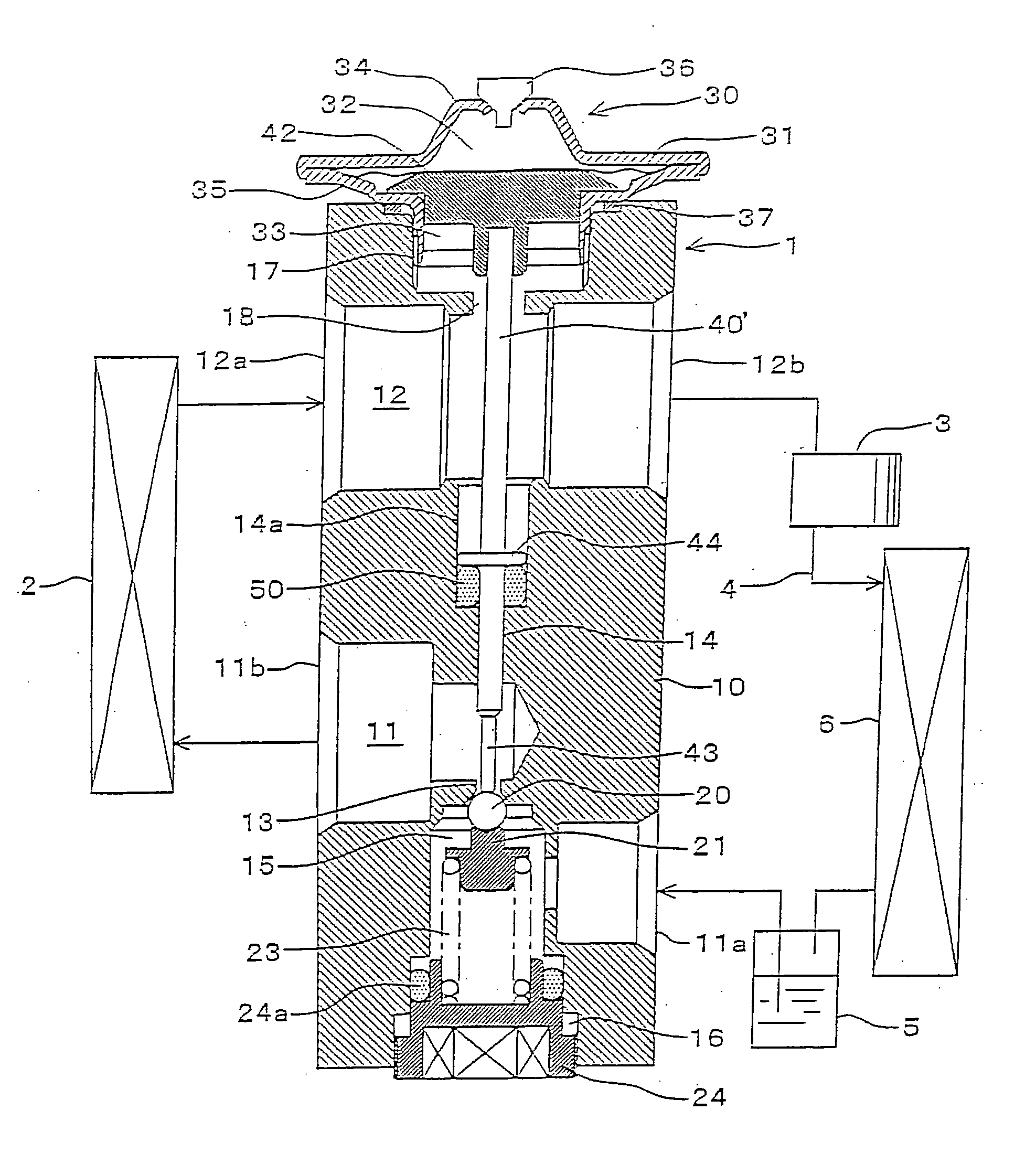
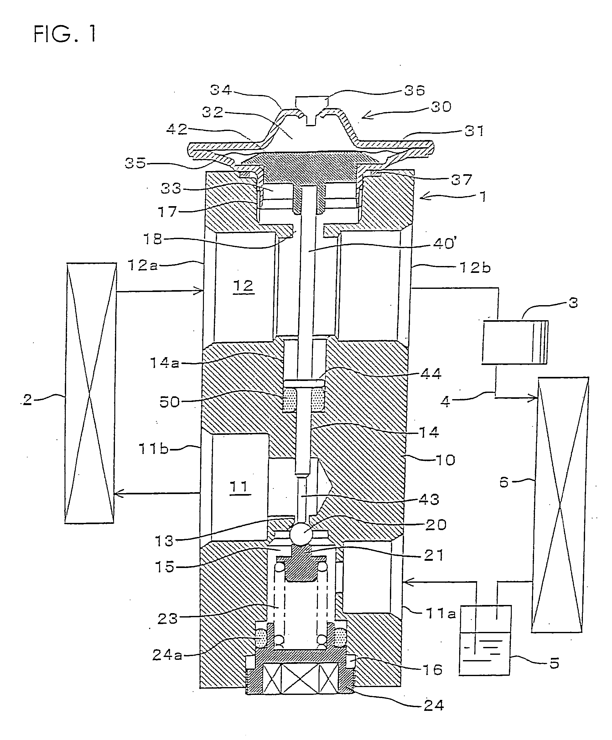
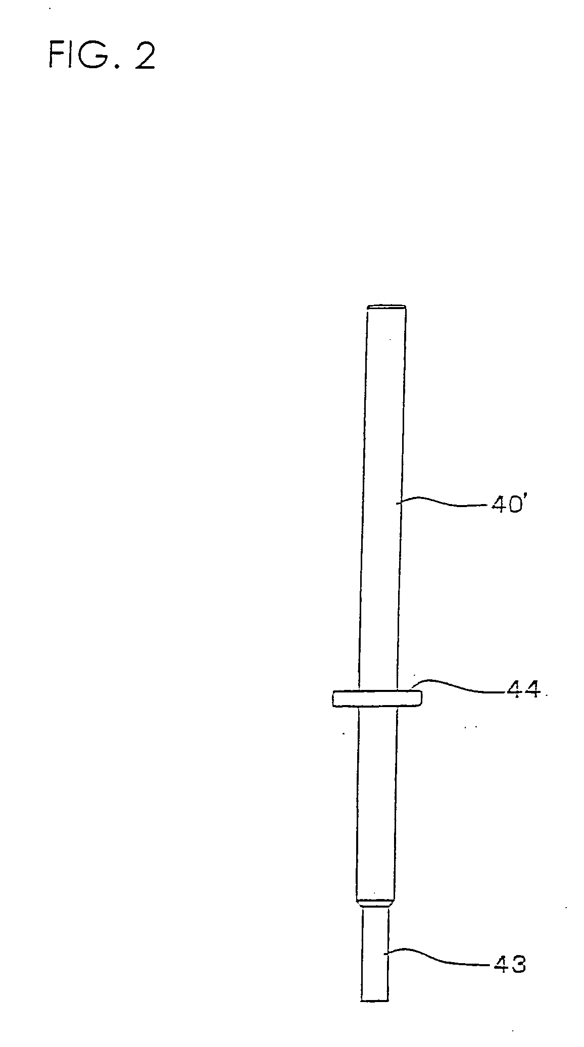
[0031] Now, the preferred embodiment of the expansion valve according to the present invention will be described with reference to the drawings. FIG. 1 is a vertical cross-sectional view of the expansion valve according to the present invention, and FIG. 2 is an explanatory view of the relevant portion of FIG. 1. According to the present embodiment, the components in FIGS. 1 and 2 that are identical to those of the prior art example illustrated in FIGS. 3 and 4 are denoted by the same reference numbers, and the explanations thereof are omitted.

[0032] At the center of a valve body 10 is disposed a rod-shaped valve actuating member 40′ made of stainless steel, similar to the prior art arrangement. That is, the valve actuating member 40′ has a top portion 42 formed in a disk-like shape with a large diameter disposed within a lower pressure actuated chamber 33 and that comes into contact with the center portion of a lower surface of a diaphragm 31. The valve actuating member 40′ is pas...


PUM


Abstract

The invention provides an expansion valve maintaining the functions of the prior art expansion valve and at the same time realizing a simple arrangement with less components and less required number of assembly steps, and enabling to cut down assembly costs. A first passage 11 through which refrigerant flowing toward an evaporator 2 travels and a second passage 12 through which refrigerant flowing from the evaporator 2 toward a compressor 3 travels are formed within a valve body 10. In response to the temperature of the refrigerant traveling in the second passage 12, a valve actuating member 40′ actuates a valve means 20 disposed in the valve body 10 to control the flow of the refrigerant entering the evaporator 2. A seal member 50 sealing the area between the first and second passages 11 and 12 is disposed between the valve body 10 and the valve actuating member 40′. A stopper portion 44 of the seal member 50 is integrally formed in advance to the valve actuating member 40′.

Description

[0001] The present application is based on and claims priority of Japanese patent application No. 2003-407821 filed on Dec. 5, 2003, the entire contents of which are hereby incorporated by reference. BACKGROUND OF THE INVENTION [0002] 1. Field of the Invention [0003] The present invention relates to an expansion valve for a refrigerant disposed in a refrigeration cycle of an air conditioner, a refrigeration device or the like. [0004] 2. Description of the Related Art [0005] Japanese Patent Laid-Open Publication No. 2000-346494 (patent document 1) discloses an example of a prior art expansion valve widely used in a refrigeration cycle of an air conditioner of a vehicle or the like. [0006]FIGS. 3 and 4 are referred to in describing the prior art expansion valve. FIG. 3 is a vertical cross-sectional view, and FIG. 4 is an explanatory view showing the relevant portion thereof. [0007] As illustrated in FIG. 3, an expansion valve 1 is formed of a rectangular column-shaped valve body 10, a...

Claims


Application Information

Patent Timeline
IPC IPC(8): F16K31/68F16K1/38F25B41/06
CPCF25B41/062F25B2500/221F25B2500/01F25B2341/0683F25B41/335F16K7/10F25B41/31F16K1/46
Inventor NANBU, AKINORIFUKUDA, SATOSHIWATANABE, KAZUHIKO
Owner FUJIKOKI CORP
Learn More