
Optical pickup apparatus, optical disc apparatus, and tracking control method thereof

Inactive Publication Date: 2006-08-29
SONY CORP
View PDF11 Cites 1 Cited by
  • Summary
  • Abstract
  • Description
  • Claims
  • Application Information

AI Technical Summary

Benefits of technology

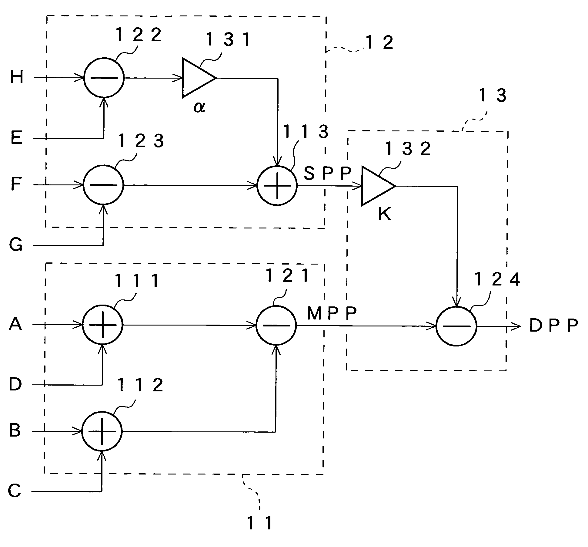
[0014]The optical pickup device according to the present invention allows an SPP signal offset to be cancelled by the calculation when the side beams are not positioned at the centers of the SPDs. The optical pickup device for performing stable tracking control during the recording may be implemented.
[0015]Namely, according to the invention, since side push-pull signal offset is cancelled with the calculation, stable tracking control may be implemented even when the side beams have different amounts of light to each other during the recording and the other. This allows recording performance (RF jitter or the like in the recorded disc) to be improved. Further, electrically adjusting the SPP signal makes tolerance for justification of optics extended and eliminates the need for a justification mechanism and an adjustment thereof This allows a cost of manufacturing the optical pickup device to be cut.
[0019]The optical disc apparatus according to the present invention allows an SPP signal offset to be cancelled by the calculation when the side beams are positioned not at the centers of the SPDs because the above optical pickup device is included in the optical disc apparatus. The optical disc apparatus for performing stable tracking control during the recording may be implemented. Thus, this invention provides inexpensive optical disc apparatus of which the recording performance can be improved.
[0022]The tracking control method for the optical disc apparatus according to the present invention allows an SPP offset to be cancelled by the calculation when the side beams of the optical pickup device are not positioned at the centers of the SPDs. This permits stable tracking control for the optical pickup device to be implemented during the recording.
[0023]Further, according to the invention, since no de-tracking occurs even when the side beams have different amounts of light to each other during the recording and the like, recording performance (RF jitter or the like in the recorded disc) may be improved. Further, electrically adjusting the SPP signal makes tolerance for justification of optics extended and eliminates the need for a justification mechanism and an adjustment thereof. This allows a cost of manufacturing the optical pickup device to be cut.

Problems solved by technology

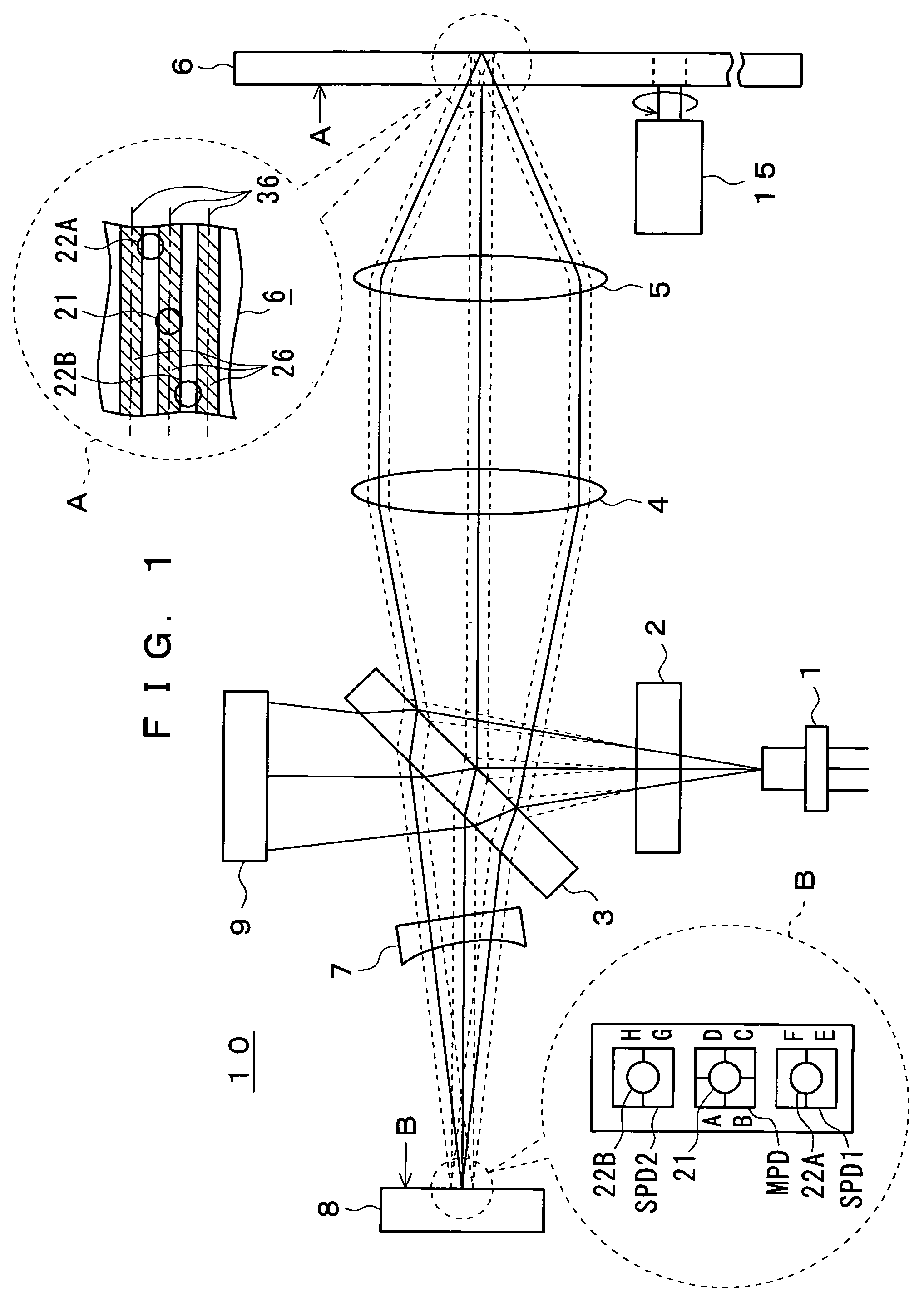
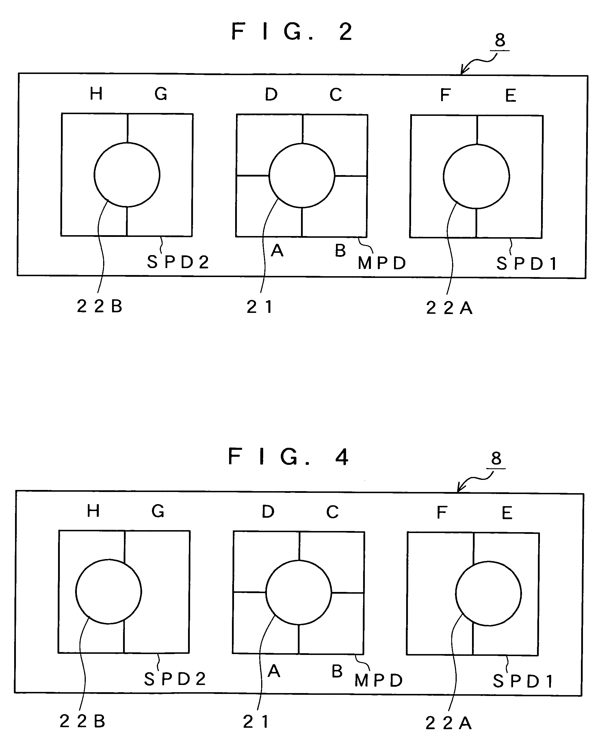
The DPP method has such a drawback that offset occurs in the SPP signal when the side beams 22A, 22b are not positioned at their center of the SPD1, SPD2 and others.
At the recording, however, they have different amplitudes, thereby failing to cancel the offset.
This causes the tracking servo error signal including the offset, resulting in some inconvenience that the tracking is unstable, at the worst case of de-tracking thereof, and the less recording performance is delivered.

Method used


Image

  • Optical pickup apparatus, optical disc apparatus, and tracking control method thereof
  • Optical pickup apparatus, optical disc apparatus, and tracking control method thereof
  • Optical pickup apparatus, optical disc apparatus, and tracking control method thereof

Examples


Embodiment Construction

[0030]The present invention has been contrived in the above circumstances by adopting a relative simple way to save the inconvenience and an object of the present invention is to provide an optical pickup device allowing stable tracking control to be implemented, which is capable of canceling the offset during the recording when side beams are not positioned at the center of each of the SPDs, an optical disc apparatus using such the optical pickup device, and a tracking control method used for the optical disc apparatus.

[0031]The optical pickup device embodying the present invention will be described more in detail with reference to the attached drawings.

[0032]The optical pickup device 10 as shown in FIG. 1 embodies the present invention and is a device for recording information on a rotationally driven optical disc and / or reproducing the information from the optical disc.

[0033]The optical pickup device 10 comprises a laser diode (light source) 1, a diffraction grating 2, a beam spl...


PUM


Abstract

After making such adjustment that an a main push-pull signal MPP offset can be made zero when a main beam is positioned at the center of a main photoreceptor, using electric signals E and F photoelectrically converted by one of two two-divided side beam photoreceptors and electric signals H and G photo-electrically converted by the other thereof, a side push-pull signal SPP including a constant α is determined for allowing respective (F−αE) and (αH−G) offsets to be made zero and is calculated according to the formula, SPP−(F−αE)+(αH−G). From this SPP signal and the main push-pull signal MPP, a differential push-pull signal DPP is then calculated, thereby allowing stable tracking control to be carried out, even during recording.

Description

TECHNICAL FIELD[0001]The present invention relates to an optical pickup device, an optical disc apparatus using the optical pickup device, and a tracking control method for controlling a tracking for the optical disc apparatus.[0002]The present invention more particularly relates to an optical pickup device and the like wherein if a differential push-pull signal is calculated from a main beam and a pair of side beams, which are reflected from the optical disc, as recording information on an optical disc and / or reproducing the information from the optical disc, the main push-pull signal is adjusted so that an main push-pull offset is made zero when the main beam is positioned at the center of a main photo-detection system and a pair of side beams are positioned at both sides of the main beam with them being symmetrical about the main beam; and then, a constant α is previously set so that offsets of the side push-pull signals are respectively made zero, thereby allowing the offsets of...

Claims


Application Information

Patent Timeline
IPC IPC(8): G11B7/095G11B7/09
CPCG11B7/0903G11B7/0943G11B7/094G11B7/09
Inventor MARUYAMA, TSUTOMUYUASA, MASAMI
Owner SONY CORP
Learn More