
Optical pickup and optical recording and reproducing device

Active Publication Date: 2015-11-05
PANASONIC INTELLECTUAL PROPERTY MANAGEMENT CO LTD
View PDF6 Cites 0 Cited by
  • Summary
  • Abstract
  • Description
  • Claims
  • Application Information

AI Technical Summary

Benefits of technology

The present disclosure provides a simple detector construction that can obtain focus error, tracking error, and RF signals with high quality, even in an optical recording / reproduction apparatus that has relatively large shift amounts of the objective lens. Additionally, this disclosure enables the simultaneous generation of signals for off-tracking detection and phase-difference TE detection. This results in a stable operation of the optical recording / reproduction apparatus with a simple construction.

Problems solved by technology

Recent years have seen upgrading in the quality of digital data such as videos, photographs, and the like, and conversion of paper media into electronic forms, and so on, which have resulted in drastic increases in their data amounts.
This results in huge amounts of data accumulation.

Method used


Image

  • Optical pickup and optical recording and reproducing device
  • Optical pickup and optical recording and reproducing device
  • Optical pickup and optical recording and reproducing device

Examples


embodiment 1

[0087]First, an optical pickup according to Embodiment 1 will be described.

[0088][1-1. Overall Construction]

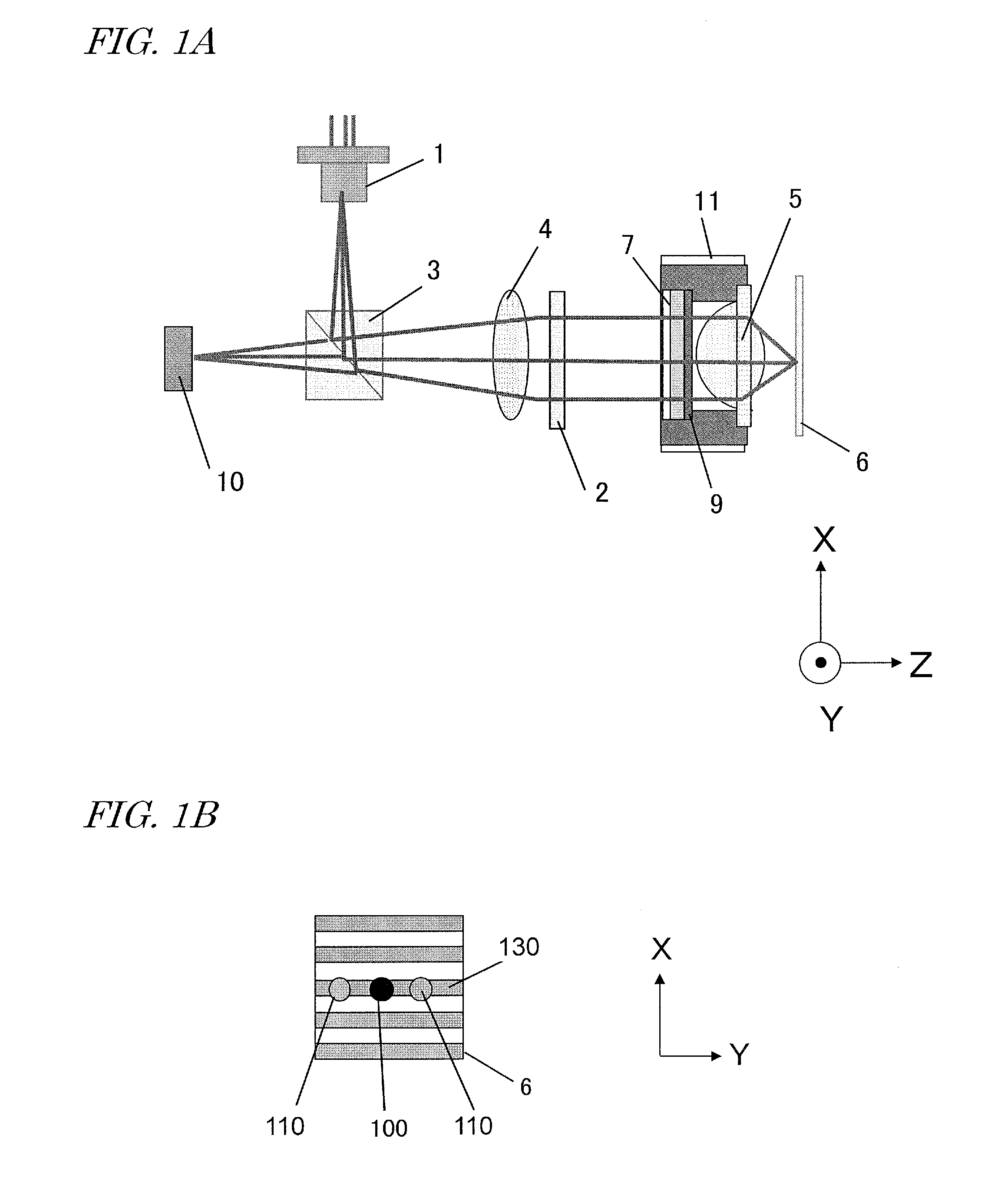
[0089]FIG. 1A is a schematic diagram showing the construction of an optical system of an optical pickup according to the present embodiment.

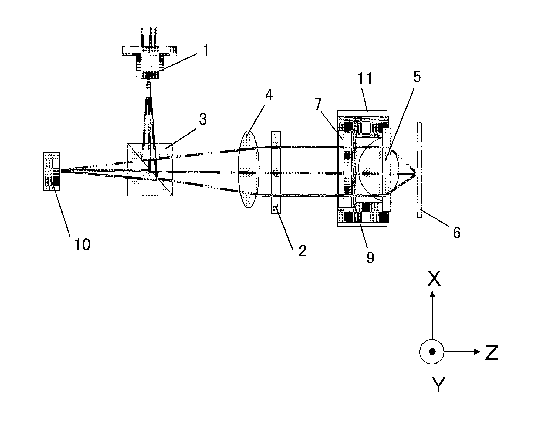
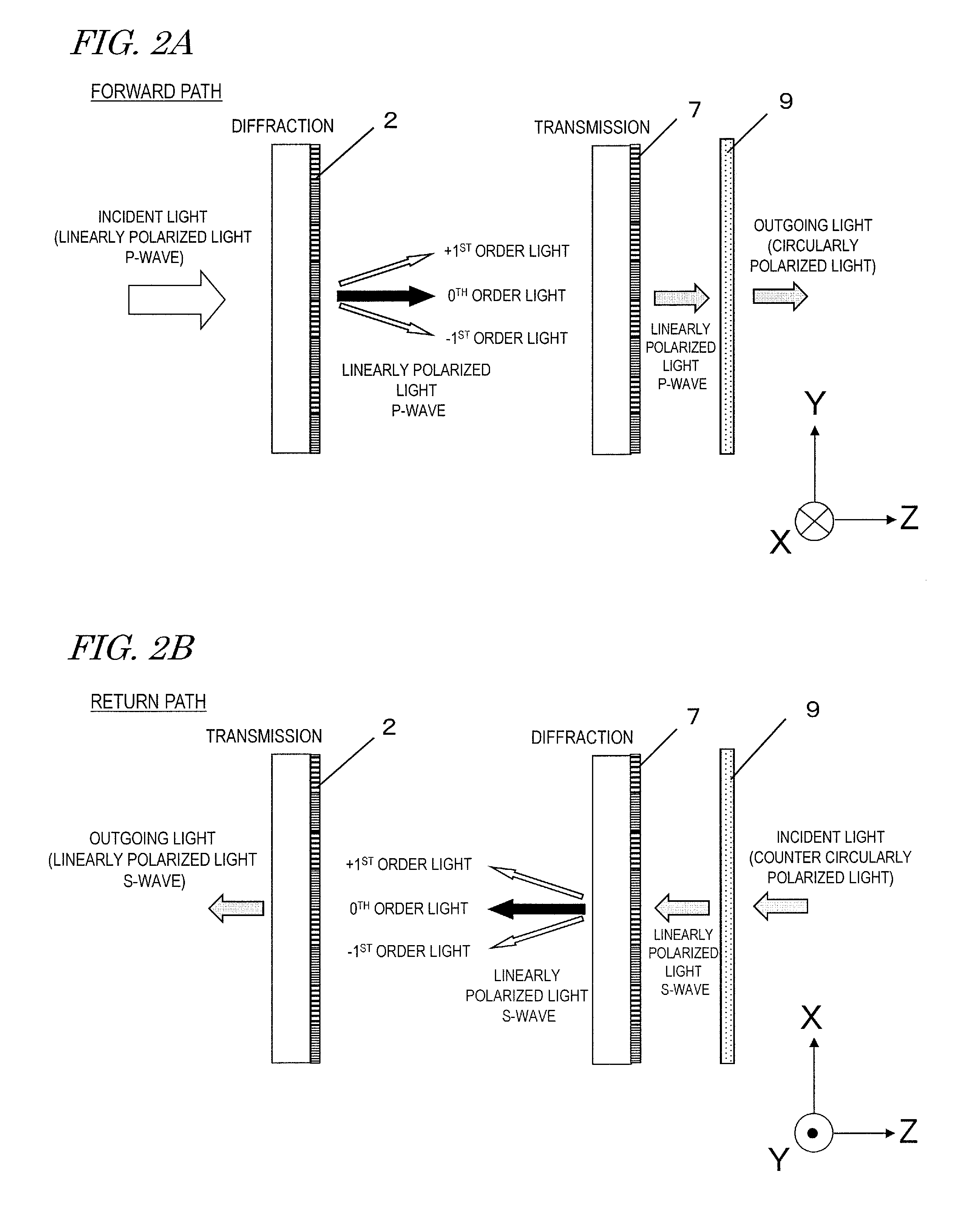
[0090]The present optical pickup includes a laser light source 1; a polarization-type diffraction element 2 for diffracting light which is emitted from the laser light source 1 so as to be split into 0th order light and ±1st order light; an objective lens 5 for converging the diffracted light onto the recording surface (recording layer) of an optical storage medium 6; a polarization-type hologram element (polarization hologram element) 7 for diffracting light which is reflected from the optical storage medium 6 so as to be split into 0th order light and ±1st order light; and a photodetector 10 for receiving the light which has been split and diffracted by the polarization hologram element 7. The optical pickup further includes a polarizati...

embodiment 2

[0169]Next, Embodiment 2 of the present disclosure will be described. The optical pickup according to the present embodiment is identical to that of Embodiment 1 except for the construction of the photodetector 10.

[0170]FIG. 7A is a schematic construction diagram of the detection system according to the present embodiment; FIG. 7B is a schematic cross-sectional view of a polarization hologram element 27 according to the present embodiment; and FIG. 7C is a diagram showing a detector pattern according to the present embodiment.

[0171]As shown in FIG. 7A, in the present embodiment, an RF signal is detected based on +1st order light derived from the main beam, similarly to servo signals, rather than being detected based on 0th order light derived from the main beam (write beam). In order to maintain the S / N ratio of the RF signal, a blazed-type polarization hologram element 27 having a periodic structure with an asymmetric cross section as shown in FIG. 7B is used. This allows the diffr...

embodiment 3

[0177]Next, with reference to FIG. 8, Embodiment 3 of the optical recording / reproduction apparatus will be described. Although the optical recording / reproduction apparatus shown in FIG. 8 is an optical disc apparatus, the optical recording / reproduction apparatus according to the present disclosure is not limited to an optical disc apparatus, but may also be an optical tape apparatus, for example.

[0178]The optical disc apparatus shown in the figure includes an optical pickup 900, a disc motor 902 which rotates an optical disc (optical storage medium) 8, and a control circuit 1000 which performs various signal processing. The optical pickup 900 is one of the optical pickups in the above-described embodiments. The control circuit 1000 has functional blocks such as a front-end signal processing section 906, a servo control section 910, an encoder / decoder 908, a CPU 909, and the like.

[0179]In the exemplary construction shown in FIG. 8, the output from the optical pickup 900 is sent to th...


PUM


Abstract

An optical pickup includes a light source 1; a diffraction element 2 for generating a write main beam and a read sub-beam via diffraction; an objective lens 5; a wavelength plate 9; a polarization hologram element 7 having a plurality of diffraction regions with different diffraction characteristics, designed so that each diffraction region separates a light beam reflected from the optical storage medium and transmitted through the wavelength plate into a 0th order light beam and ±1st order light beams; an actuator 11; and a photodetector 10 configured to detect a light beam reflected from the optical storage medium 6 and diffracted by the polarization hologram element 7. The photodetector 10 generates an RF signal from a detection result concerning a 0th order light beam derived from the main beam, generates a focus error signal and a tracking error signal from a detection result concerning one of ±1st order light beams derived from the main beam, and generates a signal indicating that data has been recorded normally from a detection result concerning a 0th order light beam derived from the sub-beam.

Description

TECHNICAL FIELD[0001]The present disclosure relates to an optical pickup and optical recording / reproduction apparatus which, at the same time of recording information on an optical storage medium such as an optical tape, simultaneously reproduces the recorded information.BACKGROUND ART[0002]Recent years have seen upgrading in the quality of digital data such as videos, photographs, and the like, and conversion of paper media into electronic forms, and so on, which have resulted in drastic increases in their data amounts. In particular, in models called cloud computing, where various applications and various services are offered for use via servers, storages, and the like which are on a network, large numbers of users save various data in the storages on the network. This results in huge amounts of data accumulation.[0003]Conventionally, magnetic tape apparatuses have often been used as storages for saving. In their place, optical tape apparatuses have been proposed which simultaneou...

Claims


Application Information

Patent Timeline
IPC IPC(8): G11B7/09G11B7/1365G11B7/1353
CPCG11B7/0903G11B7/1365G11B7/1353G11B7/00458G02B5/1871G02B5/3016G02B27/286G11B7/0912G11B7/131
Inventor ASADA, JUN-ICHITAKAHASHI, YUICHIMATSUMIYA, HIROAKIMOMOO, KAZUO
Owner PANASONIC INTELLECTUAL PROPERTY MANAGEMENT CO LTD
Learn More