Optical phase space combiner

Active Publication Date: 2013-05-16
SEOUL SEMICONDUCTOR
View PDF4 Cites 0 Cited by
  • Summary
  • Abstract
  • Description
  • Claims
  • Application Information

AI Technical Summary

Benefits of technology

[0033]In general, there is a trade-off between average brightness and PSC efficiency. For instance, assume the PSC is a hexagonal array of rotational symmetric microlenses. There is an LED chip near the focus of every microlens. The chip emission does not intercept exactly its corresponding lens. This is because the chip emission gives a spot on the lens surface that is close to having rotational symmetry whereas the lens contour is hexagonal or square. Moreover, the brightness of the rays exiting the lens is not uniform even if the chip emission has constant brightness. This is because of the Fresnel losses associated with the air gap between chips and PSC are strongly dependent on the angle of incidence for large incidence angles. These losses are high for those rays that intercept the border of the lens. So in general we will have lower brightness for rays issuing from the border of a lens than for the rays issuing from its center, i.e., there will be a non-constant illuminance

Problems solved by technology

In general, the optics problem consists of transmitting the light emitted by the LEDs to a target with a prescribed irradiance pattern.
Thermal management: Because LED chips are tightly packed in the SCO strategy; heat extraction is much more difficult in this case than in the MIO strategy.
Electrical interconnections: The tight package of the SCO strategy makes electrical interconnections and chip electrical isolation more difficult than in the MIO strategy, although this may be a relatively small problem for some soldering technologies.
Optical system manufacturing and assembling: This is the weakest aspect of the MIO

Method used


Image

  • Optical phase space combiner
  • Optical phase space combiner
  • Optical phase space combiner

Examples


Embodiment Construction

[0048]A better understanding of various features and advantages of the present invention may be obtained by reference to the following detailed description of the invention and accompanying drawings, which set forth illustrative embodiments in which the principles of the invention are utilized.

[0049]Optics for combining several ray bundles into a single ray bundle has been designed with two different techniques.

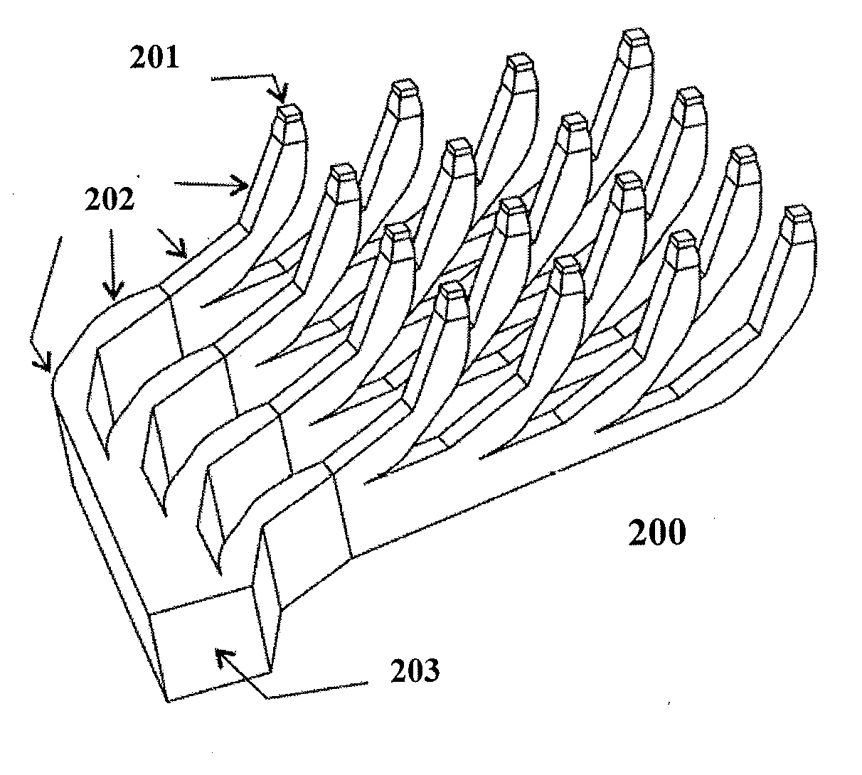
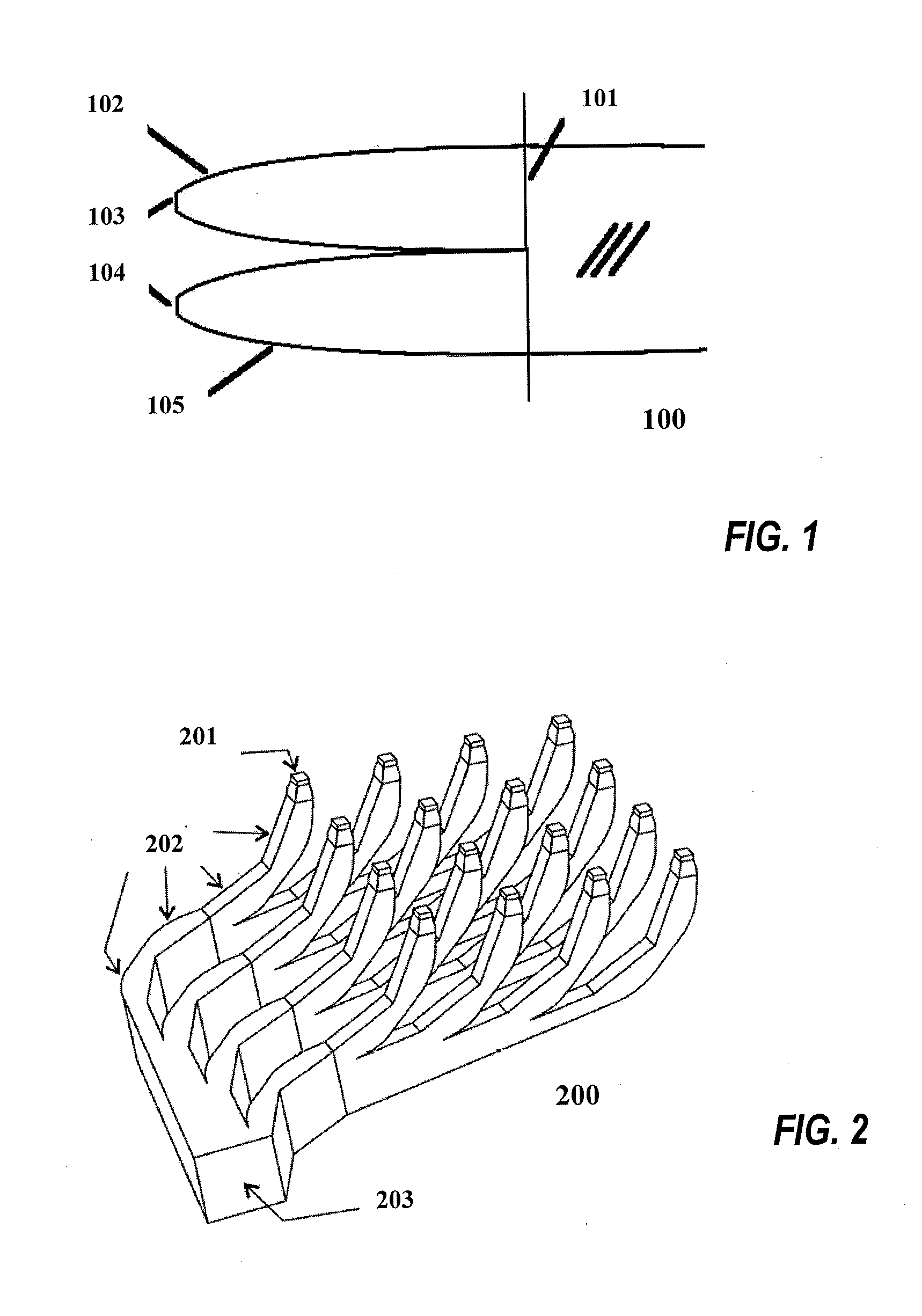
[0050]FIG. 1 shows a phase space combiner (PSC) 100 of prior art designed with the flow-line method based on U.S. Pat. No. 7,286,296 B2. A “flow-line” is a line that at every point is tangent to the bisector of the angle formed by the edge rays of the rays from the source reaching that point after being modified by any structures that add or remove rays between the original source and the point of measurement. An “ortho-flowline” is a line that at every point is perpendicular to the flow-lines. The light from two sources 103 and 104 is combined to create a single bigger sourc...


PUM


Abstract

An optical component called the Phase Space Combiner (PSC) is designed to join several bundles of rays. The bundles of rays, when represented in ray phase-space, occupy non-connected regions before passing through the PSC, while their representation in ray phase space occupies a single simply connected region (without holes) after passing through the PSC. Obviously, when used in reverse way it splits one bundle in several parts. We present herein the idea of using Multiple Individual Optics, MIO, not for collimating the light from the LEDs but as a PSC. Then a Single Common Optics, SCO, which can be an optical train, is used to get the desired intensity pattern. This hybrid SCO and MIO strategy combines most of the advantages of both approaches.

Description

CROSS REFERENCE TO RELATED APPLICATION[0001]This application claims benefit of U.S. Provisional Patent Application No. 61 / 629,253, filed Nov. 16, 2011 by Miñano et al. for “Optical Phase Space Combiner.” References are made to commonly owned U.S. Pat. No. 7,286,296 B2 titled “Optical Manifold For Light-Emitting Diodes” by Chaves et al., to U.S. Pat. No. 8,000,018 B2 titled “Kohler Concentrator” by Benitez et al, and to U.S. Patent Application Publication No. 2008 / 0316761 A1 titled “Free-Form Lenticular Optical Elements and Their Application to Condensers and Headlamps” by Miñano et al. These applications, which have at least one common inventor to the present application, are incorporated herein by reference in their entirety.BACKGROUND OF THE INVENTION[0002]In solid state illumination, when high brightness together with high flux, or when high brightness together with color tuning, are required, the only possibility is to use several high brightness LEDs (HBLEDs), or multi-chip LED...

Claims


Application Information

Patent Timeline
IPC IPC(8): G02B27/14
CPCG02B27/14G02B19/0028G02B19/0066
Inventor MINANO, JUAN CARLOSPABLO, BENITEZ
Owner SEOUL SEMICONDUCTOR
Why Eureka
Try Eureka