Cap for MEMS package

a technology of cap and mems, applied in the direction of electrical apparatus construction details, electrical apparatus casings/cabinets/drawers, coupling device connections, etc., can solve the problems of reducing the cutting rate and costing a lot of time, and achieve the effect of reducing the time needed for the process of mems packag

Active Publication Date: 2012-08-07
LINGSEN PRECISION INDS
View PDF4 Cites 0 Cited by
  • Summary
  • Abstract
  • Description
  • Claims
  • Application Information

AI Technical Summary

Benefits of technology

[0007]The present invention has been accomplished in view of the above-noted circumstances. It is an objective of the present invention to provide a cap for a MEMS package, which can minimize the time needed for the MEMS package process.
[0008]To attain the above objective, the present invention provides a cap for a MEMS package, which comprises a main body having a bottom surface, a top surface, a plurality of accommodations recessed from the bottom surface towards the top surface, and a plurality of slots recessed from the top surface towards the bottom surface in a way that the top surface is defined into a plurality of regions corresponding to the accommodations respectively. After the cap provided by the present invention is bonded on a substrate on which a plurality of MEMS dies are provided, the finished package can be cut along the slots into a plurality of MEMS units. In the cutting process, since the to-be-cut thickness of the cap is equal to the distance defined between the bottom portion of the slot and the bottom surface of the main body, which is smaller than the total thickness of the main body of the cap, the cutting work can be done more quickly and the cutting burrs can be minimized. Further, the more the area of the cap can be provided the less the number and times of the caps that are needed to be bonded on the substrate per unit area can be obtained. As a result, the cap provided by the present invention can reduce the bonding times of the cap needed for the MEMS package process and can increase the cutting rate and minimize the cutting burrs occurred during the cutting process, dramatically cutting down the processing time of the MEMS package process.

Problems solved by technology

However, since the cutting tool has to cut the bonded substrate 20 and cap 22 at a time in the cutting step, the cutting rate will be reduced and the cutting burrs will occur, such that a fine polishing work for removing the cutting burrs needs to be introduced after the cutting step, costing a lot of time.

Method used


Image

  • Cap for MEMS package
  • Cap for MEMS package
  • Cap for MEMS package

Examples


Embodiment Construction

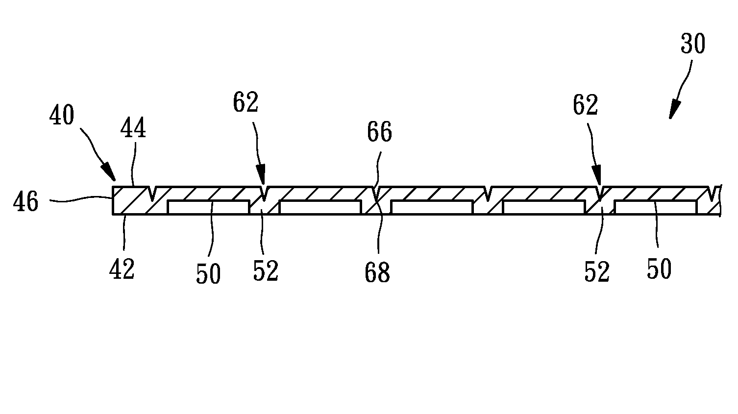
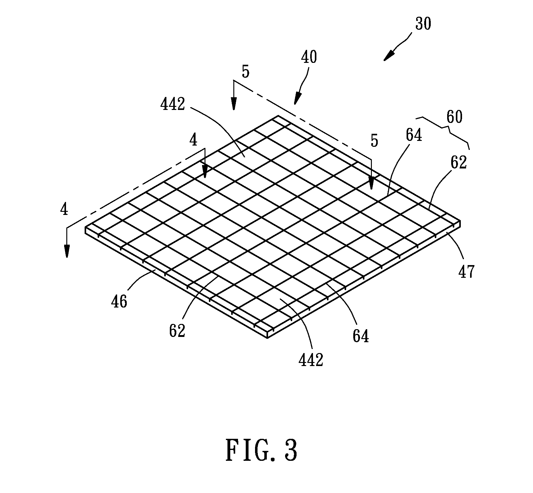
[0018]As shown in FIGS. 3-5, the cap, denoted by reference numeral 30, in accordance with a preferred embodiment of the present invention is used for a MEMS package. The cap 30 includes a main body 40 having a plurality of accommodations 50 recessed from a bottom surface 42 of the main body 40 towards a top surface 44 of the main body 40 at a predetermined depth, and a plurality of slots 60 recessed from the top surface 44 towards the bottom surface 42 at a predetermined depth.

[0019]The accommodations 50 each have a rectangular cross-section and are arranged in a matrix format including ten rows of the spaced and parallel accommodations 50 and seven columns of the spaced and parallel accommodations 50, in which every two rows of the accommodations 50 are separated by a transverse partition wall 52 as shown in FIG. 4, and every two columns of the accommodations 50 are separated by a longitudinal partition wall 54 as shown in FIG. 5.

[0020]The slots 60 each have an elongated shape when...


PUM


Abstract

A cap for a MEMS package includes a main body having a bottom surface, a top surface, a plurality of accommodations recessed from the bottom surface towards the top surface, and a plurality of slots recessed from the top surface towards the bottom surface in a way that the top surface is defined into a plurality of regions corresponding to the accommodations respectively. After completion of the MEMS package, the package can be cut along the slots into a plurality of MEMS package units, such that the cutting work can be done quickly and the cutting burrs can be minimized.

Description

BACKGROUND OF THE INVENTION[0001]1. Field of the Invention[0002]The present invention relates generally to cap packages of Micro-Electro-Mechanical System (hereinafter referred to as “MEMS”) and more particularly, to a cap for use in a MEMS package.[0003]2. Description of the Related Art[0004]FIG. 1 is a schematic drawing showing a step of making a conventional MEMS package. After a substrate 10, which is basically defined on its top surface into a plurality of regions 13 on each of which a die 12 is bounded, is provided, a plurality of caps 14 are mounted on the substrate 10 one by one for protecting the dies 12 respectively. Thereafter, the substrate 10 thus obtained is cut along the gaps between the regions 13 into a plurality of MEMS package units each containing the die 12. In the step of mounting the caps 14 on the regions 13 of the substrate 10, conductive adhesive is used to mount the caps 14 one by one, resulting tin that the aforesaid mounting step is time-consuming. In ad...

Claims


Application Information

Patent Timeline
Patent Type & Authority Patents(United States)
IPC IPC(8): H01R4/22
CPCB81C1/00269B81C1/00888
Inventor YEH, JEN-CHUANLEE, KUO-TING
Owner LINGSEN PRECISION INDS
Why Eureka
Try Eureka