Device for establishing noise in a motor vehicle

a technology for establishing noise and motor vehicles, which is applied in the direction of combustion-air/fuel-air treatment, charge feed systems, instruments, etc., can solve the problems of inability to provide the optimum solution in particular with regard to more flexible transmission characteristics, low efficiency, and relatively small noise affecting the interior space, so as to improve the influence of noise in the interior space and intensify the vibration of the interior lining elemen

Inactive Publication Date: 2005-06-09
DAIMLER AG
View PDF11 Cites 40 Cited by
  • Summary
  • Abstract
  • Description
  • Claims
  • Application Information

AI Technical Summary

Benefits of technology

[0008] A deflecting element according to the invention between the outlet line and the interior lining element has the effect that the sound waves that are produced by the sound transmission device and introduced to the vehicle interior via the outlet line are deflected in the direction of the interior space, whereby an intensification of the sound effect is achieved. This intensified sound effect leads to a force acting on the deflecting element, which then, on account of the connection of the deflecting element to the inner lining element, induces the latter to undergo vibrations and in this way provides further intensification of the sound effect.
[0009] Therefore, in addition to changing the sound radiation there is also the advantageous effect that vibrations of the interior lining element are produced, so that overall considerably improved influencing of the noise in the interior space is possible by the device according to the invention, enabling the driver to acoustically perceive the load state of the engine.
[0010] The interior space of the motor vehicle can be insulated considerably better in this way for protection from disturbing external noises, without depriving the driver of acoustic information concerning the load state of the engine.
[0011] Decoupling the outlet line from the deflecting element, and the resultant possibility of intensifying the vibrations of the interior lining element induced by the sound can be achieved if, in an advantageous development of the invention, a flexible connecting element is arranged between the outlet line and the deflecting element.

Problems solved by technology

The disadvantages of this known device, however, are its relatively low efficiency and the very inflexible transmission characteristics.
However, an optimum solution in particular with regard to more flexible transmission characteristics is still not provided.

Method used


Image

  • Device for establishing noise in a motor vehicle
  • Device for establishing noise in a motor vehicle
  • Device for establishing noise in a motor vehicle

Examples


Embodiment Construction

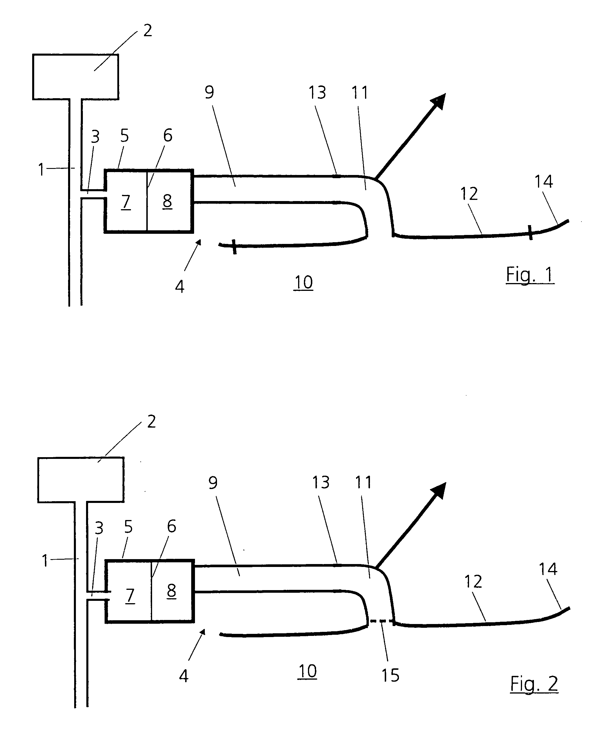
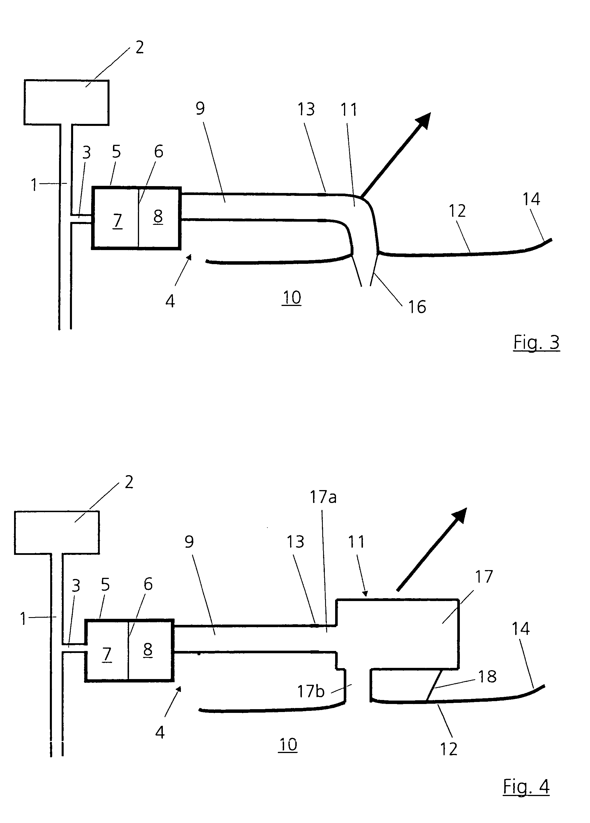
[0020]FIG. 1 shows a gas-carrying line 1 of an internal combustion engine 2, which may be an exhaust line or an intake line of the engine 2. From the gas-carrying line 1, an inlet line 3 leads to a device 4 for establishing engine noise in the interior of a motor vehicle, which is not represented in its entirety the engine 2 being mounted in the motor vehicle in a way known per se.

[0021] The device 4, the basic construction and operating principle of which are known for example from DE 100 42 012 A1, has a hollow body 5, in the interior of which there is arranged a sound transmission device. The sound transmission device in the present case is formed as a vibratable membrane 6 and divides the hollow body 2 into two spaces, namely an inlet space 7 and an outlet space 8. Of these, the inlet space 7 is connected to the inlet line 3 and the outlet space 8 is connected to an outlet line 9 which leads to an interior space 10 of the motor vehicle.

[0022] Vibrations or sound waves inside t...


PUM


Abstract

In a device for establishing noise in a motor vehicle, comprising a housing which is divided by a sound transmission device into at least two spaces, of which one space is in communication with a gas-carrying part of an internal combustion engine arranged in the motor vehicle and the other space is acoustically coupled to an interior space of the motor vehicle via an outlet line, the outlet line is connected via a hollow rigid deflecting element to an interior space lining element, the rigid deflecting element being capable of transmitting forces applied thereto by the sound radiation to the interior space lining element.

Description

[0001] This is a continuation-in-part application of international application PCT / EP03 / 03480 filed Apr. 3, 2003 and claiming the priority of German application 102 23 872.3 filed May 29, 2002. BACKGROUND OF THE INVENTION [0002] The invention relates to a device for establishing noise in a motor vehicle including a housing which is divided by a sound transmission device into at least two spaces of which one is in communication with a gas-carrying part of an internal combustion engine of the motor vehicle and the other space is acoustically coupled to the vehicle interior. [0003] Such a device is known, for example, from DE 44 35 296 A1. Such devices are intended to transmit the noises produced by the internal combustion engine more intensely to the driver of the motor vehicle, in particular during acceleration, in order, on the one hand, to provide for a more intensive driving experience and, on the other hand, to provide to the driver more information concerning the load state of t...

Claims


Application Information

Patent Timeline
Patent Type & Authority Applications(United States)
IPC IPC(8): F01N1/02F01N1/08G10K11/22
CPCF02M35/1294G10K11/22
Inventor HOFMANN, MARCUSSTAROBINSKI, ROUDOLF
Owner DAIMLER AG
Why Eureka
Try Eureka