Flow control device for fluids

Inactive Publication Date: 2005-06-09
MARK IV SYST MOTEURS USA
View PDF10 Cites 11 Cited by
  • Summary
  • Abstract
  • Description
  • Claims
  • Application Information

AI Technical Summary

Benefits of technology

[0004] The object of the present invention is to provide a duct for the passage of fluids, which is

Problems solved by technology

Control devices of the type described above, although universally used, are not normally very suited for use in cases in which it is necessary to control, with a relatively high degree of precision, the flow of fluid through the above-mentioned port when the shutter member ass

Method used


Image

  • Flow control device for fluids
  • Flow control device for fluids
  • Flow control device for fluids

Examples


Embodiment Construction

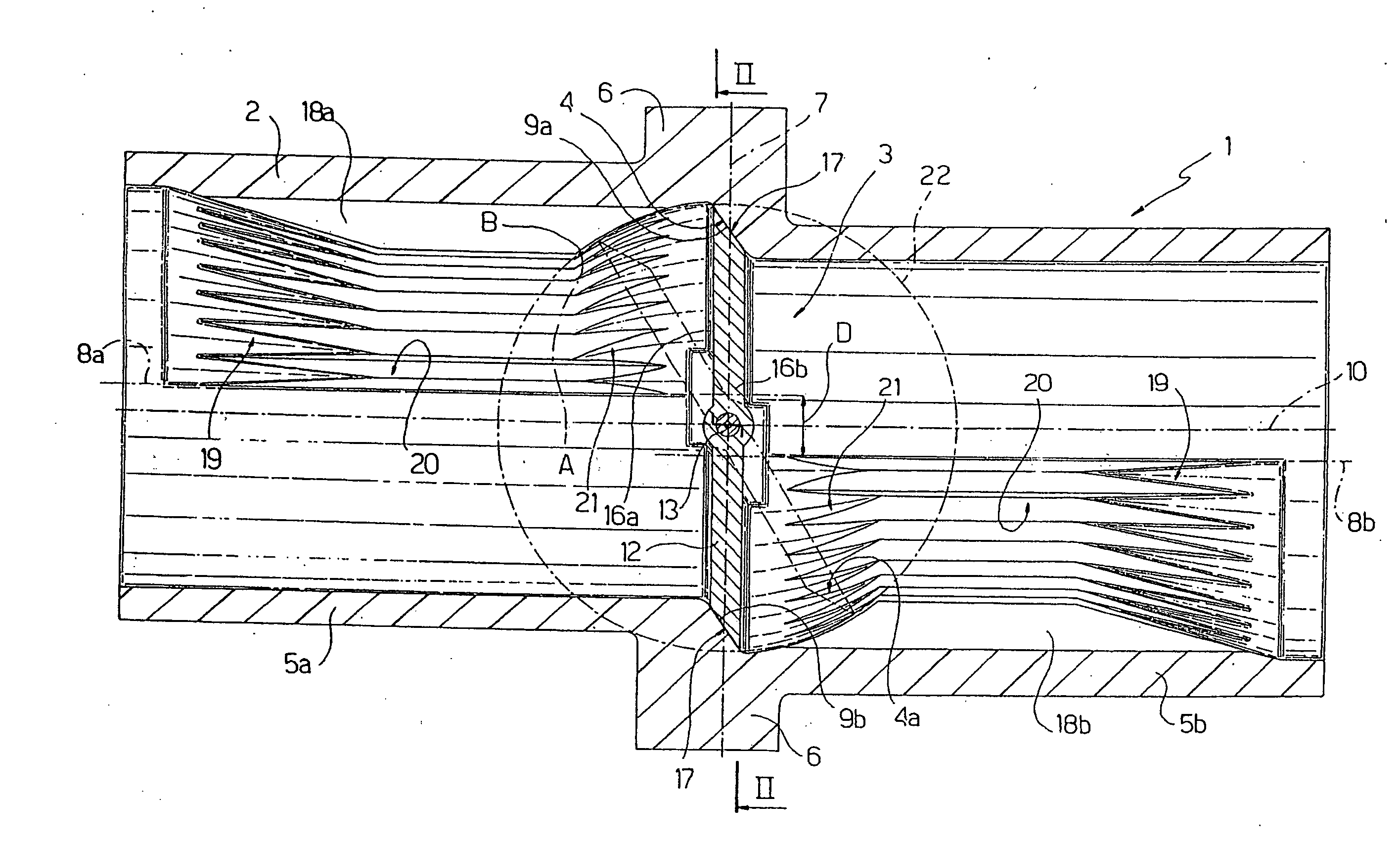
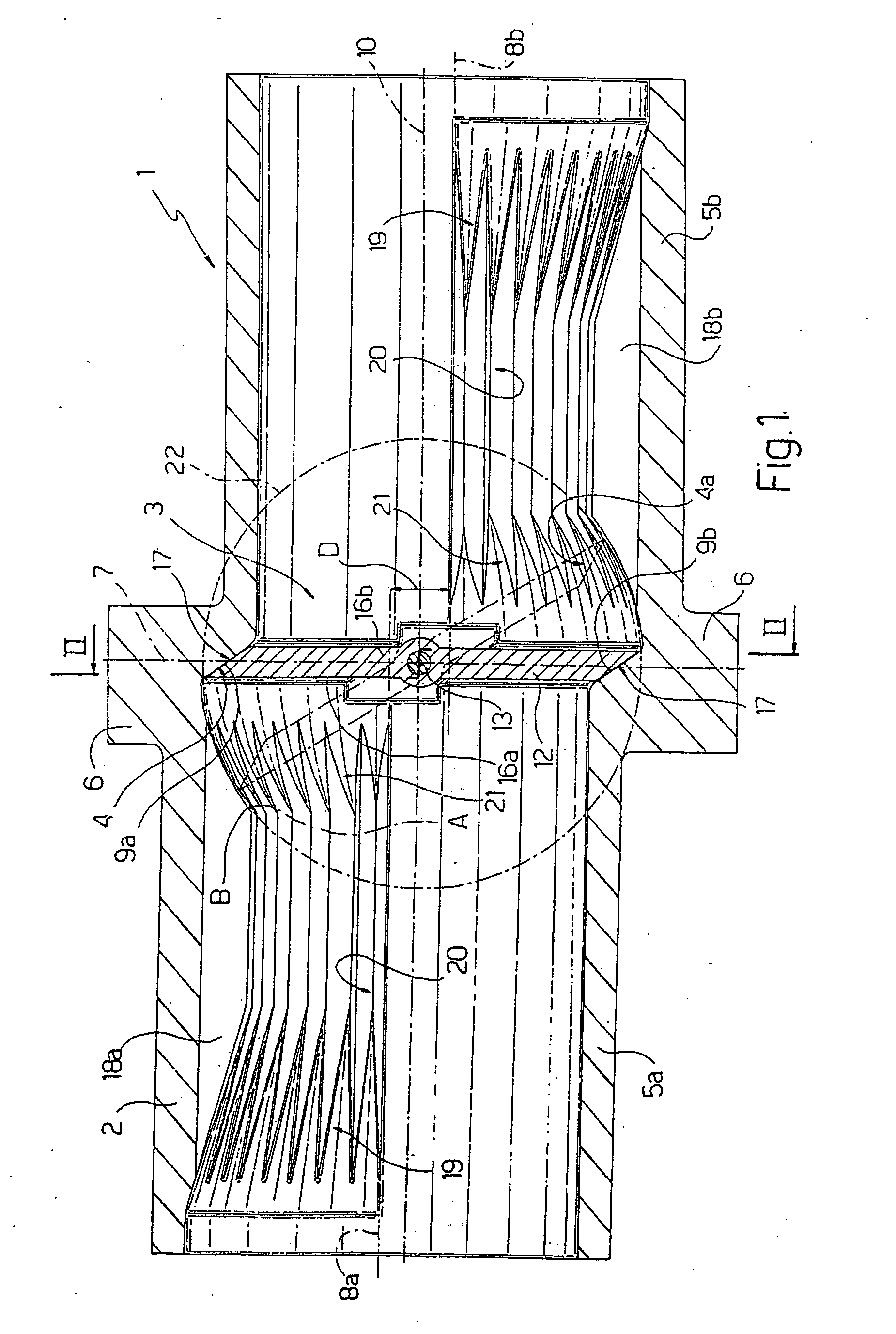
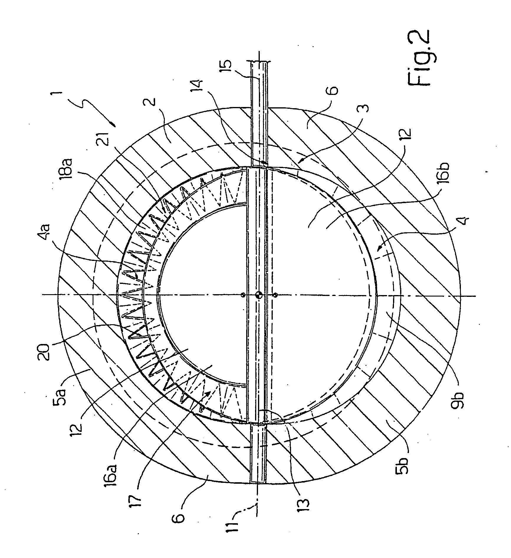
[0010] In FIGS. 1 and 2, a flow control device for fluids is shown overall by 1 and comprises a duct 2 and a moving shutter member 3 housed in the duct 2 at the location of its annular seat 4 and adapted to be displaced with respect to the seat 4 in order to vary the working flow section of a fluid through a port 4a formed by this seat 4.

[0011] The duct 2 comprises two cylindrical portions 5, shown respectively by 5a and 5b, having substantially identical inner diameters and disposed upstream and downstream respectively of the seat 4. The portions 5 are connected together at the location of respective flanges 6 in contact with one another along a transverse median plane 7 of the seat 4 and have respective longitudinal axes 8a and 8b which are parallel to one another and perpendicular to the transverse median plane 7, both lie in the plane of FIG. 1 and are disposed at a predetermined distance D from one another with the longitudinal axis 8a disposed, in FIG. 1, above the longitudin...


PUM


Abstract

A flow control device (1) for fluids in which a duct (2) has a predetermined inner port (4a) controlled by a moving shutter member (3) and is provided, on each side of the moving shutter member (3), with a fixed shutter member (18) having a predetermined shape and adapted to cooperate with the moving shutter member (3) to define a hydraulic resistance varying according to a predetermined law which is a function of the shape of the fixed shutter member (18).

Description

TECHNICAL FIELD [0001] The present invention relates to a flow control device for fluids. [0002] The present invention relates more particularly to a flow control device for fluids of the type comprising a duct having a predetermined inner port and a shutter member for the port mounted to move within the duct. BACKGROUND ART [0003] Control devices of the type described above, although universally used, are not normally very suited for use in cases in which it is necessary to control, with a relatively high degree of precision, the flow of fluid through the above-mentioned port when the shutter member assumes positions close to a position of total closure of the port, since relatively small displacements of the moving shutter member from its closed position generally cause relatively high variations of the flow of fluid through the port controlled by the moving shutter member. DISCLOSURE OF THE INVENTION [0004] The object of the present invention is to provide a duct for the passage ...

Claims


Application Information

Patent Timeline
IPC IPC(8): F16K1/22F16K47/08
CPCF16K47/08F16K1/22
Inventor LOLLI, SERGIO
Owner MARK IV SYST MOTEURS USA
Why Eureka
Try Eureka