Direct-current uninterruptible power source unit

a power source unit and direct current technology, applied in the direction of emergency power supply arrangement, secondary cell servicing/maintenance, electrochemical generators, etc., can solve the problems of deteriorating condition, difficult battery replacement by users, and difficult battery replacement operation

Inactive Publication Date: 2005-06-09
PANASONIC CORP
View PDF12 Cites 93 Cited by
  • Summary
  • Abstract
  • Description
  • Claims
  • Application Information

AI Technical Summary

Benefits of technology

[0009] Accordingly, the present invention has been made in view of the foregoing problems of the conventional technique and has an object of providing a DC uninterruptible power source unit, which simply replaces only a deteriorated rechargeable battery at any timing as a result of monitoring a deteriorating state of the rechargeable battery.

Problems solved by technology

These uninterruptible power source units are equipped with an inverter, and when a trouble such as power failure or the like occurs in a commercial power, the units convert a DC power into an AC power through the inverter and supply the DC power to a load device, for example, a computer.
However, the rechargeable battery has a usual life span of 3 to 6 years, and a deteriorating condition of the battery varies depending upon conditions used or stored.
However, since, according to the replacement of the rechargeable batteries in the conventional technique, all the rechargeable batteries are taken out all together and then the deteriorated rechargeable batteries out of all are designed to be replaced.
Also a replacement operation of the batteries is not easy since a plurality of rechargeable batteries are first disconnected, then replaced, and again the plurality of the rechargeable batteries are connected.
Accordingly, it is difficult to perform the battery replacement by a user.

Method used


Image

  • Direct-current uninterruptible power source unit
  • Direct-current uninterruptible power source unit
  • Direct-current uninterruptible power source unit

Examples


Embodiment Construction

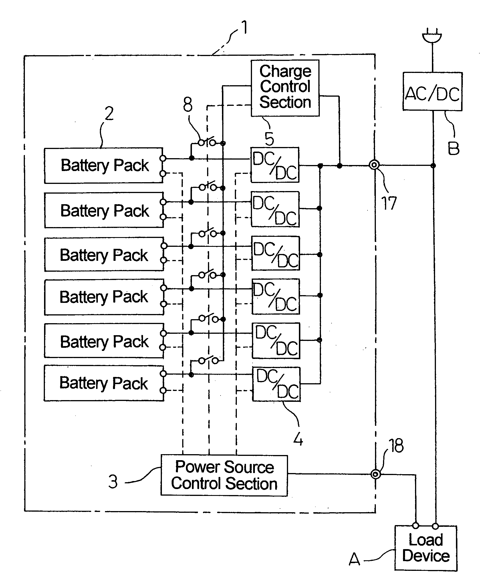
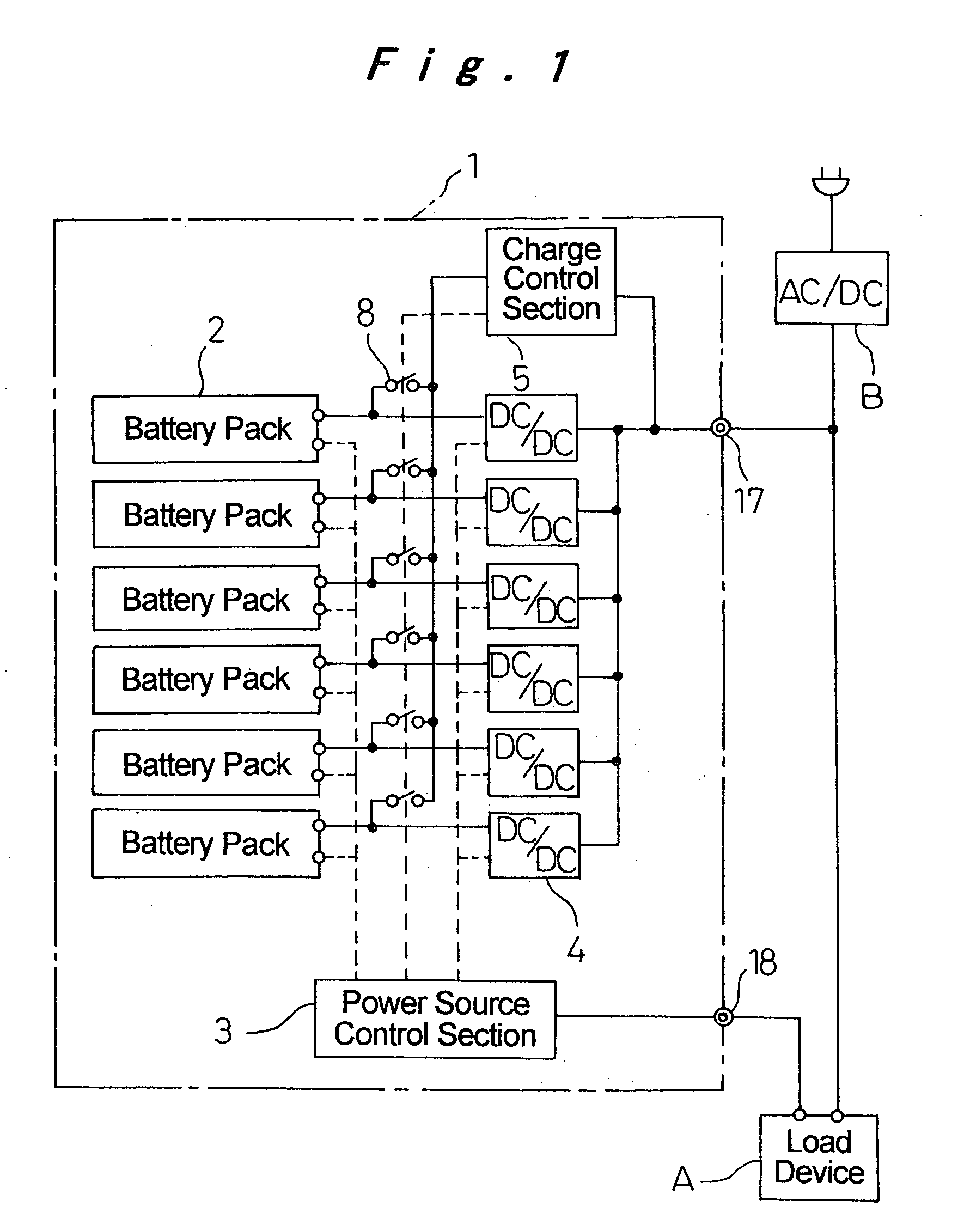
[0025]FIG. 1 shows the configuration of a DC uninterruptible power source unit 1 according to an embodiment of the invention. The DC uninterruptible power source unit 1 is constituted of a backup power source on occurrence of a power source trouble such as a power failure in a power source of a load device A such as a computer device. The load device A operates by supply of a DC power obtained by converting a commercial power into a direct current by an AC / DC conversion device B. When the power source trouble such as a power failure occurs in the commercial power as an AC power source, the DC power is supplied from the DC uninterruptible power source unit 1 to prevent occurrence of damage such as data destruction in the load device A.

[0026] A predetermined number of battery packs 2 to output the DC power having a voltage corresponding to a DC power source voltage required by the load device A are mounted in the DC uninterruptible power source unit 1. The DC uninterruptible power so...


PUM

PropertyMeasurementUnit
output voltageaaaaaaaaaa
charge poweraaaaaaaaaa
voltageaaaaaaaaaa

Abstract

Battery packs with a plurality of rechargeable batteries connected in series so as to obtain a voltage required by a load device are detachably accommodated in a case. The battery packs are connected in parallel and each output thereof is modified to a predetermined voltage by a discharge control section. The battery packs are connected to a power source line of the load device. Each battery pack is connected through an information transmission line to a power source control section where charge and discharge thereof are controlled, as well as the lifetime is judged. Thus, only the lifetime-judged battery pack is replaced.

Description

[0001] The present disclosure relates to subject matter contained in priority Japanese Patent Application No. 2003-410626, filed on Dec. 9, 2003, the contents of which is herein expressly incorporated by reference in its entirety. BACKGROUND OF THE INVENTION [0002] 1. Field of the Invention [0003] The present invention relates to a DC uninterruptible power source unit, which supplies a backup power to a load device when a power supply trouble occurs, wherein the load device is operated by a DC power provided from an AC / DC conversion device converting an AC power supplied from an AC power source into the DC power. [0004] 2. Description of the Related Art [0005] An uninterruptible power source unit is used to protect from a power source trouble a computer in which a crucial defect such as data destruction caused by cutting off a power supply or the like tends to occur. Known uninterruptible power source units include, for example, an on-line type power supply system, a line interactiv...

Claims


Application Information

Patent Timeline
Patent Type & Authority Applications(United States)
IPC IPC(8): H01M10/44H02J1/00H02J7/00H02J7/02H02J7/34H02J9/00H02J9/06
CPCH01M10/345H01M10/441H02J9/06H02J7/0024H02J7/0042H01M10/482Y02E60/10
Inventor MATSUMOTO, ATSUOOKAMOTO, SEIICHISHIGEMOTO, RYOJIHATABE, MASANORI
Owner PANASONIC CORP
Why Eureka
Try Eureka