Brush holder assembly for an electric motor

a brush and electric motor technology, applied in the field of electric motors, can solve the problems of insufficient rebound, rapid wear of both brushes and commutators, and insufficient rebound of snap fingers to adequately hold the tube in place, so as to reduce the lateral play of the cage

Active Publication Date: 2005-06-09
JOHNSON ELECTRIC SA
View PDF22 Cites 9 Cited by
  • Summary
  • Abstract
  • Description
  • Claims
  • Application Information

AI Technical Summary

Benefits of technology

[0024] Preferably, the method includes the step of using the resiliency of the deformed second set to barbs to provide a lateral pretension on the brush cage to reduce lateral play of the cage within the through hole.

Problems solved by technology

If the tube's internal dimensions are too small, the brush will not slide and if it is too big, the brush will wobble within the tube causing sparking on the commutator leading to rapid wear of both brush and commutator.
Another disadvantage is that the snap finger is not very resilient and often does not rebound enough to adequately hold the tube in place.
To overcome this problem, the recess for the finger is made bigger to ensure clearance between the finger and the edge of the recess but this allows axial movement of the brush tube which also leads to sparking under vibration.
While some motors do not use a brass brush cage but allow the brush to slide directly in the through hole of the bearing bracket, this is not acceptable for high speed and high power motors where positioning and heat dissipation are critical issues.

Method used


Image

  • Brush holder assembly for an electric motor
  • Brush holder assembly for an electric motor
  • Brush holder assembly for an electric motor

Examples


Embodiment Construction

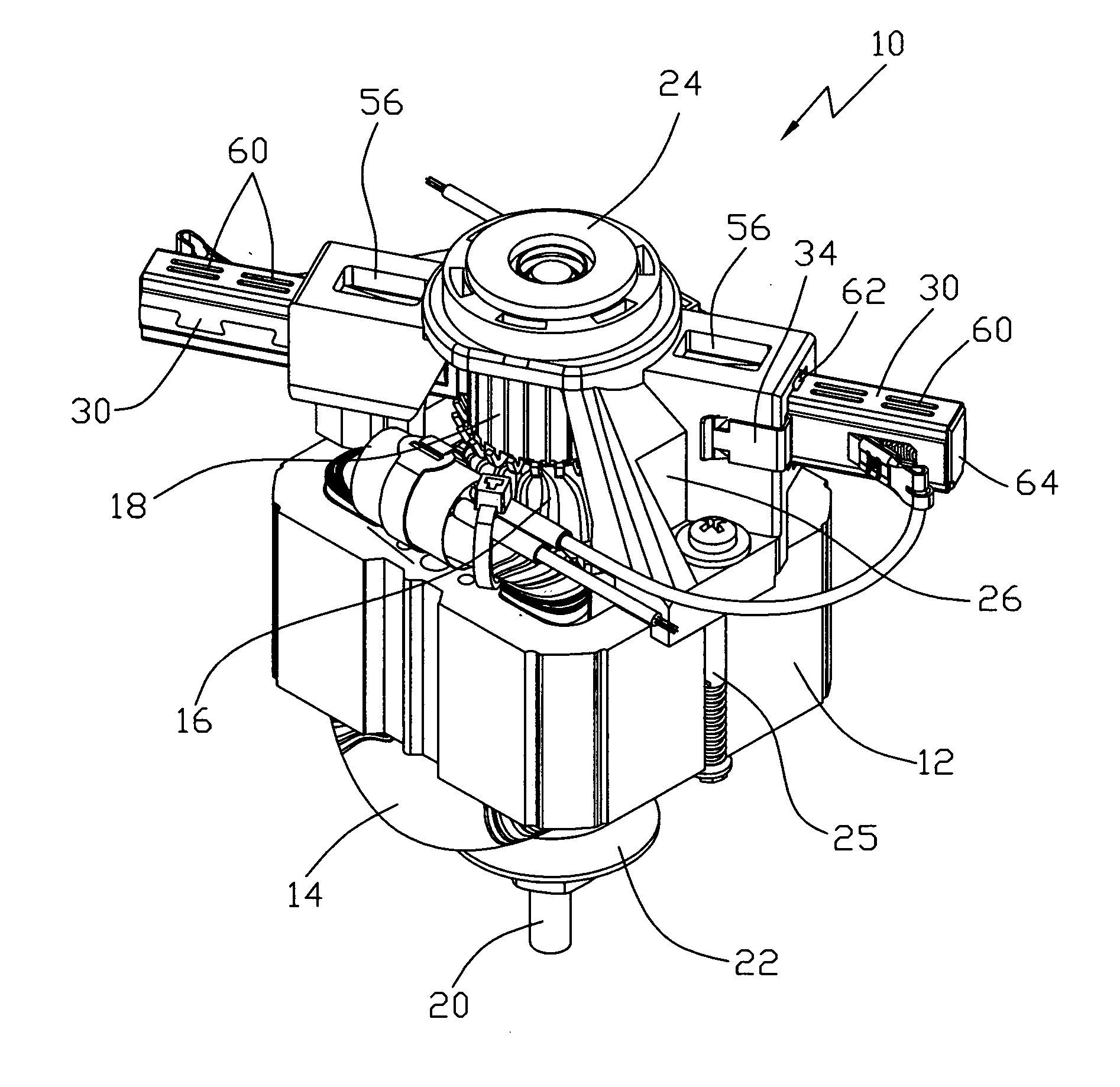
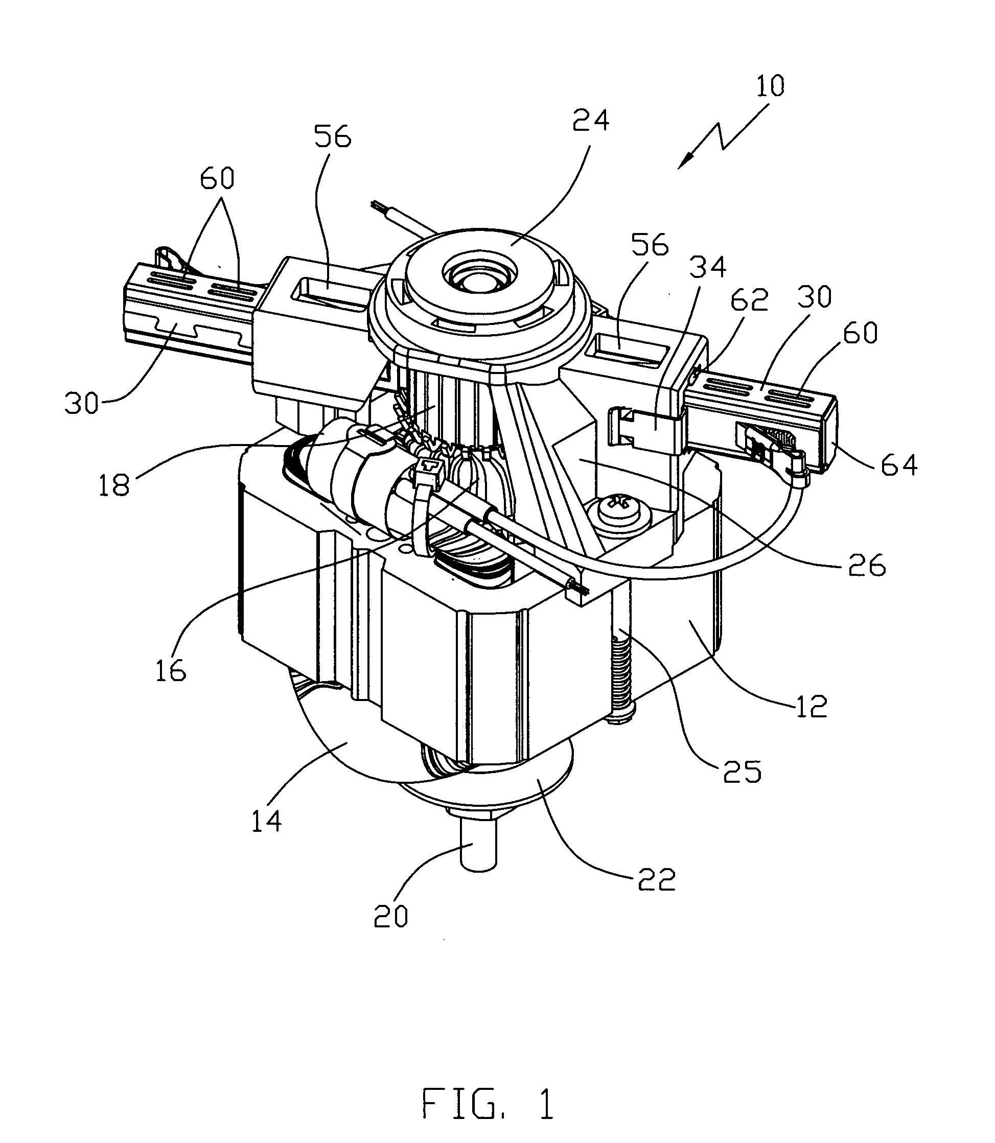
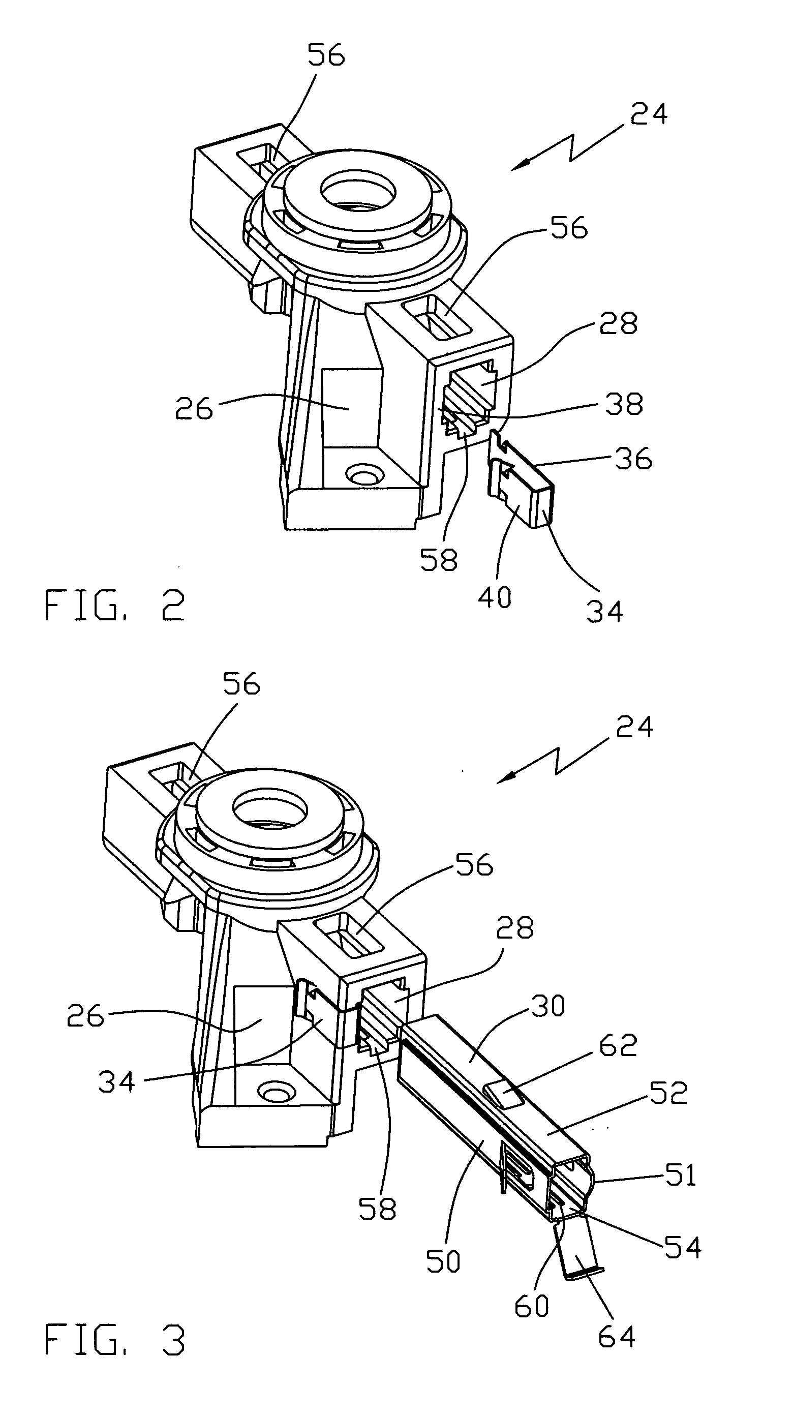
[0032] The present invention will be illustrated by describing a preferred embodiment of the brush assembly as used in a universal motor as shown in FIG. 1. The universal motor 10 has a laminated stator core 12 supporting stator windings 14. A wound rotor 16, including a commutator 18 and a shaft 20 is located extending through the stator core 12. An output bearing bracket 22 is fixed to one axial end of the stator core. An input bearing bracket 24 is fixed to the other axial end of the stator core 12. The bearing brackets 22, 24 are fixed to the stator core 12 by bolts 25 which extend through holes in the brackets 22, 24 and through or along side the stator core 12. Both brackets 22, 24 support bearings in which the shaft 20 is journalled. The output bracket 22 is U-shaped and may include additional holes for mounting of the motor to an appliance. The input bracket 24 is also U-shaped and the commutator is located between the legs 26 of the input bracket. Each leg of the input brac...


PUM


Abstract

A universal motor has a brush cage assembly in which a U-shaped clip 34 is located about a wall of a through hole 28 of a bearing bracket 24 for receiving a brush cage 30. The clip 34 has an outer limb 42 with inwardly and rearwardly directed barbs 44 to grip an outer surface of the wall to prevent removal of the clip 34 and an inner limb 36 with outwardly and forwardly directed barbs 42 which resiliently deform as the cage 30 is inserted to snare the cage 30 should it move in the opposite direction. The clip 34 thus prevents withdrawal of the brush cage 30 and provides a lateral spring force against the cage 30 to reduce cage lateral position tolerance and movement.

Description

CROSS-REFERENCE TO RELATED APPLICATIONS [0001] This non-provisional patent application claims priority under 35 U.S.C. § 119(a) from Patent Application No. 0328386.8 filed in Great Britain on Dec. 6, 2003. FIELD OF THE INVENTION [0002] This invention relates to electric motors and in particular, to a brush holder assembly for a small electric motor. BACKGROUND OF THE INVENTION [0003] Many small brush type electric motors, such as fractional horsepower universal type motors and miniature dc motors have brush cages for guiding brushes into contact with a commutator. It is common for the brush cages to be essentially brass tubes in which the brushes slide under the influence of a brush spring. The brush tubes are fixed to the motor structure to ensure accurate location of the position of contact between the brush and the commutator. Often the motor structure includes a bearing bracket of plastic or similar insulating material and the brass tubes are pressed into holes in the bearing br...

Claims


Application Information

Patent Timeline
Patent Type & Authority Applications(United States)
IPC IPC(8): H01R39/38H01R39/415H02K5/14H02K5/16H02K5/173H02K13/00
CPCH01R39/385H02K5/148H02K5/1732
Inventor KONG, JOHNNYCRESTANI, VIRGILIO
Owner JOHNSON ELECTRIC SA
Why Eureka
Try Eureka