Barrier closure system

a barrier closure and barrier technology, applied in the direction of ac motor stoppers, door/window fittings, building components, etc., can solve the problems of reducing the sensitivity of the sensor, the capacitance between the two sensors in the closed position can be much larger,

Inactive Publication Date: 2005-06-09
PATHMINDER
View PDF3 Cites 14 Cited by
  • Summary
  • Abstract
  • Description
  • Claims
  • Application Information

AI Technical Summary

Benefits of technology

[0005] An object of the present invention is

Problems solved by technology

For a capacitance edge sensor this poses a problem because the capacitance between the housing in the open position and between the two sensors in the closed position can be much larger than the change caused by the pres

Method used


Image

  • Barrier closure system
  • Barrier closure system
  • Barrier closure system

Examples


Embodiment Construction

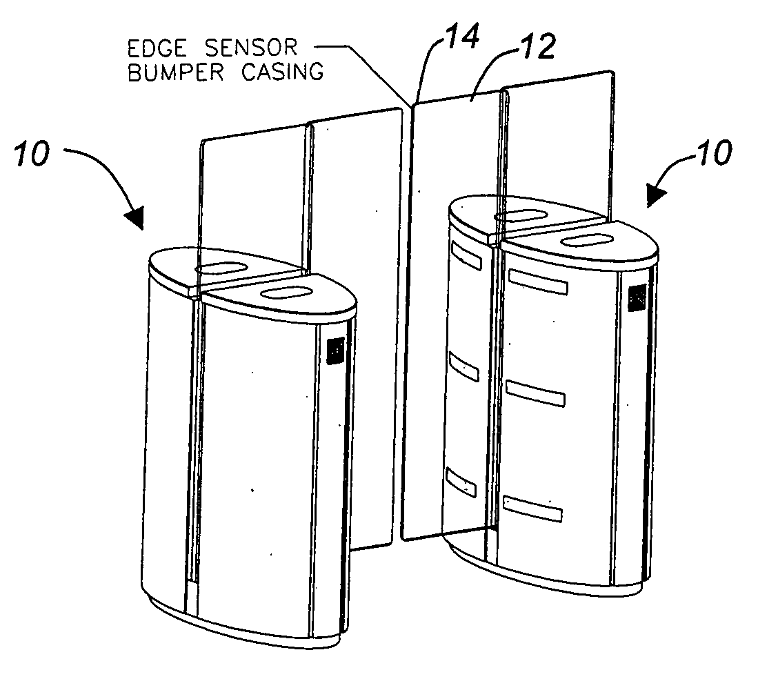
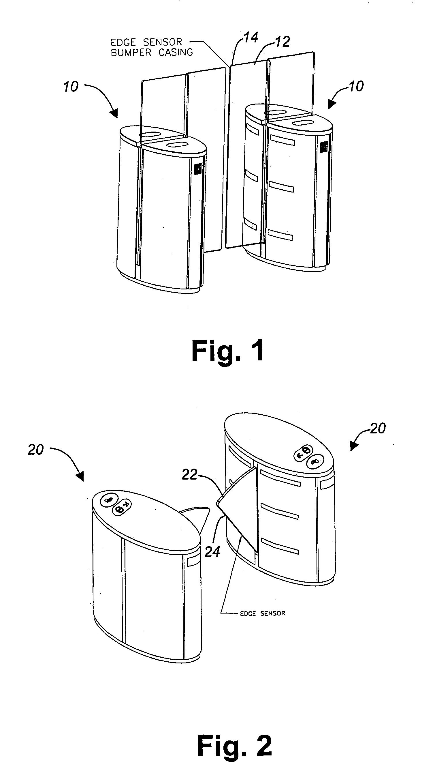
[0022] Referring to FIG. 1, there is illustrated a pair of turnstiles with sliding doors including a sensor for detecting obstructions in accordance with an embodiment of the present invention. Each turnstile 10 includes a sliding gate 12 having an edge-mounted sensor 14.

[0023] Referring to FIG. 2, there is illustrated a pair of turnstiles with angel wing doors or gates including a sensor for detecting obstructions in accordance with an embodiment of the present invention. Each turnstile 20 includes a pivoting gate 22 having an edge-mounted sensor 24.

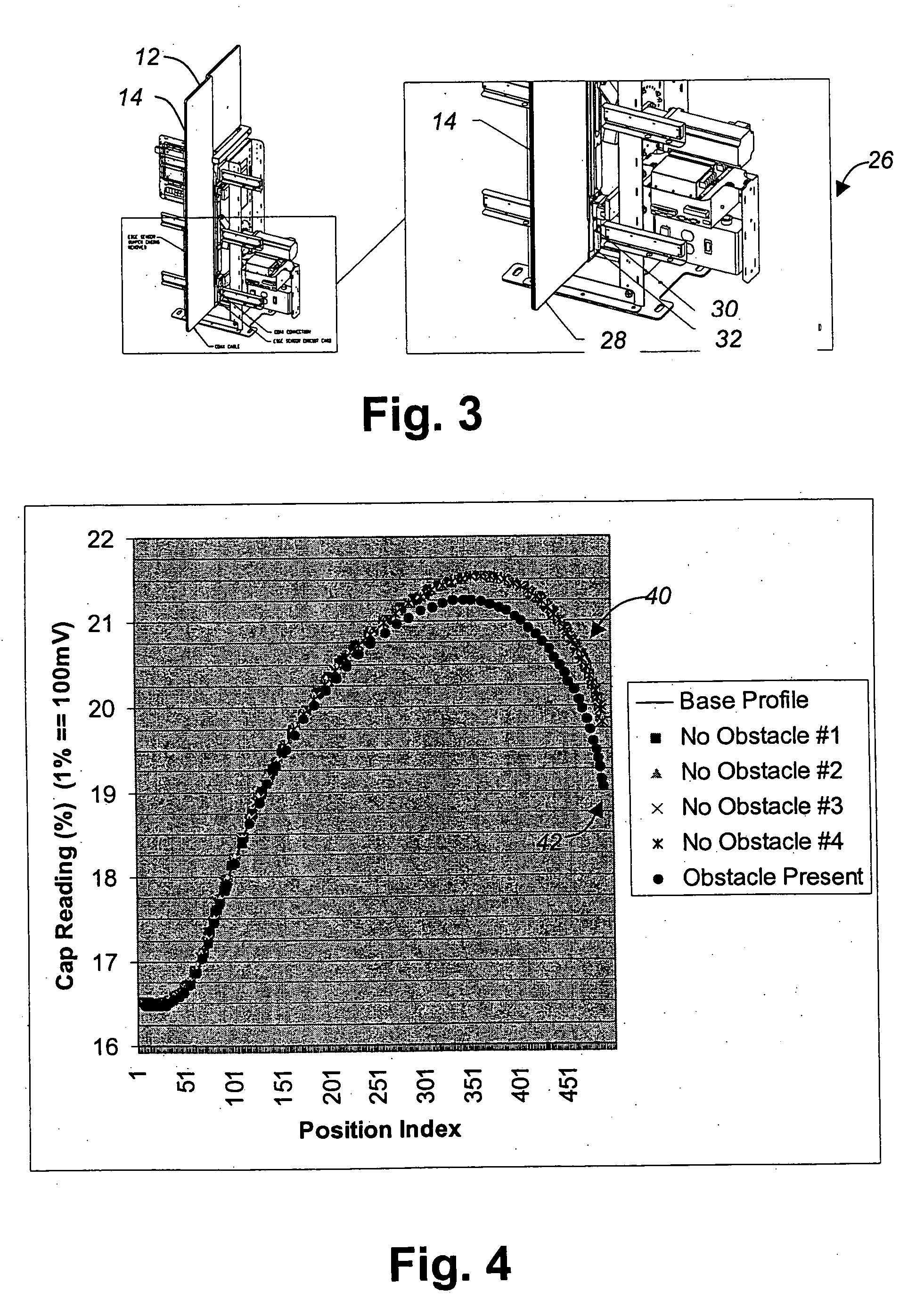
[0024] Referring to FIG. 3, there is illustrated in a perspective view detail of one turnstile of FIG. 1. The internal gate closure mechanism is shown with outer housing removed. A detailed section thereof 26 shows a portion of the sliding gate 12 with its edge-mounted sensor 14 connected via a coaxial cable 28 and a coax connector 30 to a sensor circuit card 32.

[0025] Referring to FIG. 4, there is graphically illustrated a capacitan...


PUM


Abstract

An obstacle detection method and system for a barrier closure system comprising a sensor for measuring a predetermined parameter as it varies during a closure of a barrier. Memory stores the measured parameter to establish a first parameter profile and a threshold value associated therewith. A detection module compares a current value of the predetermined parameter to a corresponding barrier position of the first parameter profile and if the current value differs by more than a threshold value sets an obstacle detection state. Conveniently the profile is recalibrated to compensate for changes in the barrier closure system such as wear, and environmental conditions that may vary over time. Preferably the sensor includes a capacitance component.

Description

FIELD OF THE INVENTION [0001] The present invention relates to barrier closure systems and is particularly concerned with obstruction detection. BACKGROUND OF THE INVENTION [0002] For automatic barriers such as gates or doors it is important to stop the gate motion when an obstruction is in the path of the gate. This issue has typically been addressed with mechanical contact sensors, for example as is commonly seen on elevator doors. Another approach is the use of beams, typically infrared, located next to the gate, or other non-contacting sensors, such as capacitance sensors taught in U.S. Pat. No. 5,337,039 and U.S. patent application 2003 / 0071727 published 17 Apr. 2003. [0003] For opposed sliding gates, that is one gate coming from each side of an opening and moving horizontally, it is desirable to have the gates come close together in the closed position and retract fully into the housing when in the open position. For a capacitance edge sensor this poses a problem because the c...

Claims


Application Information

Patent Timeline
IPC IPC(8): E05F15/00E06B11/08H02P1/00
CPCE05Y2900/40E05F15/40E06B11/085
Inventor PATCHELL, JOHNPOTTNER, BERND
Owner PATHMINDER
Why Eureka
Try Eureka