Electronic camera having color adjustment function and program therefor

Inactive Publication Date: 2005-06-09
NIKON CORP
View PDF6 Cites 35 Cited by
  • Summary
  • Abstract
  • Description
  • Claims
  • Application Information

AI Technical Summary

Benefits of technology

[0072] Here, it is able to know occurrence of a color fog caused by the special light source in a wide range of the shot image in a case where a color fog is detected in a part (i.e., a low-chroma region) of the shot image in which the illumination is judged even. In this case, the electronic camera corrects the color fog by adjusting the color balance to reduce the separation of the chromaticity of the shot image from the black body locus. As a result, the degrees of the color fogs occurring in th

Problems solved by technology

Such color temperature unevenness in the same frame makes it very difficult to perform proper white balance adjustments.
However, the conventional apparatus cannot obtain an image captured with flash and an image captured without flash at the same time; the two images are always generated with a time difference.
Therefore, for an object that moves at high speed in a frame, it is difficult to judge influences of a flash on the basis of luminance differences between two kinds of images and it is impossible to perform proper white balance adjustments.
Therefore, use of the conventional apparatus leads

Method used


Image

  • Electronic camera having color adjustment function and program therefor
  • Electronic camera having color adjustment function and program therefor
  • Electronic camera having color adjustment function and program therefor

Examples


first embodiment

Operation of First Embodiment

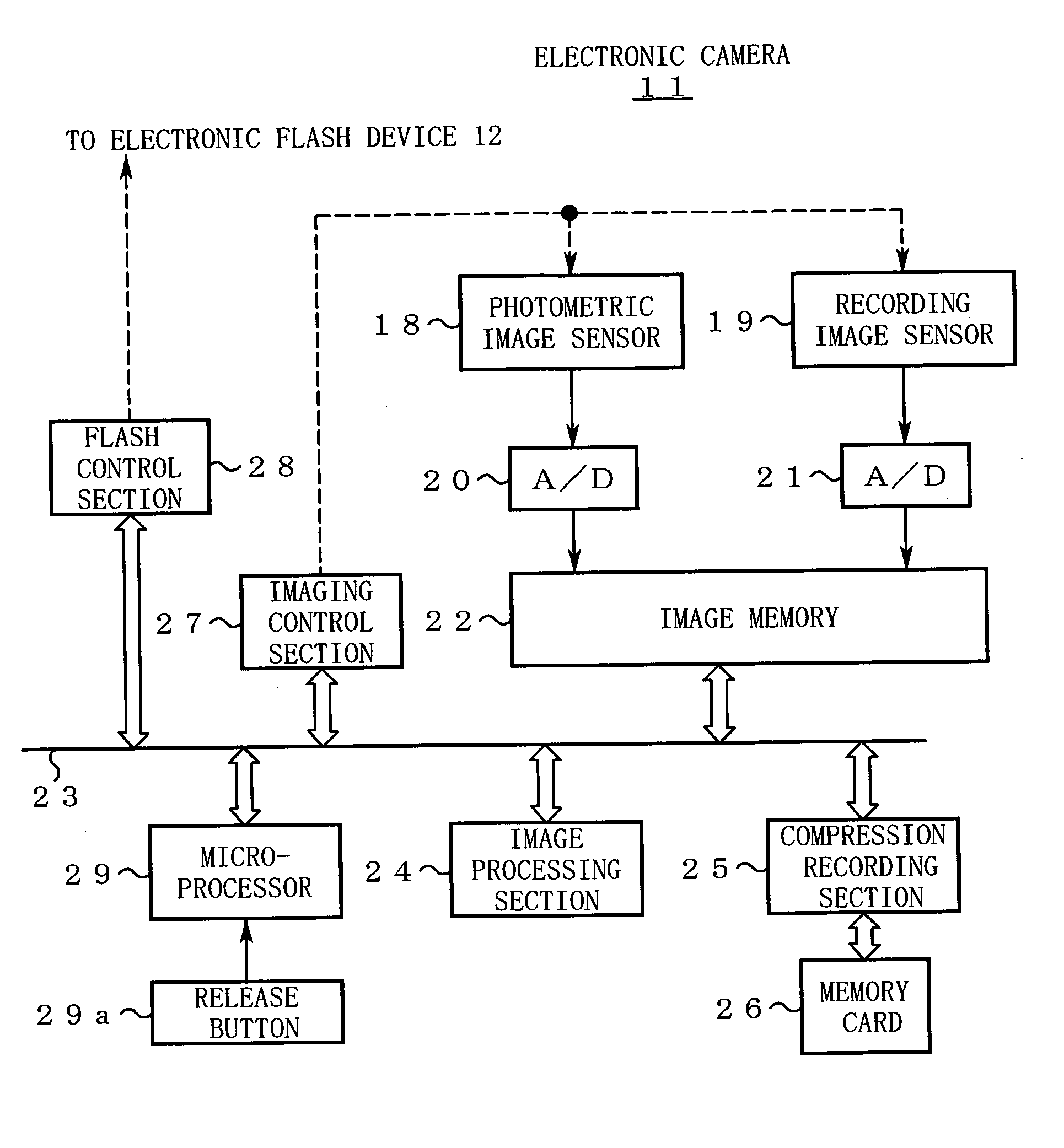
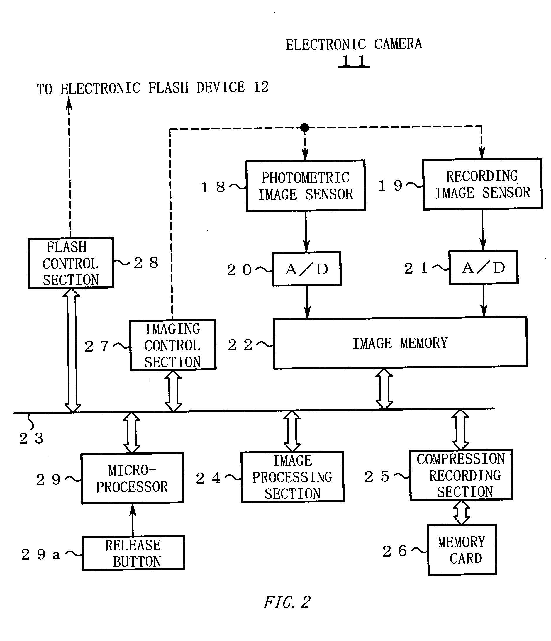
[0095]FIG. 3 is a flowchart showing the operation of the first embodiment. The operation of the electronic camera 11 will be described below in order of step numbers shown in FIG. 3.

[0096] [Step S1] When the main power of the electronic camera 11 is turned on, the microprocessor 29 starts initialization processing to be performed at the time of power application. In the initialization processing, the microprocessor 29 acquires information relating to a color temperature of a flash from the electronic flash device 12 and calculates a first white balance adjustment value suitable for the color temperature.

[0097] [Step S2] The microprocessor 29 judges whether the electronic camera 11 is in a flash-shooting mode.

[0098] If the flash-shooting mode is not set, the microprocessor 29 makes a transition to an ordinary photographing routine (not shown) to perform known ordinary photographing. In the ordinary photographing routine, an image shot with the photomet...

second embodiment

Operation of Second Embodiment

[0158]FIG. 6 is a flowchart showing the operation of the second embodiment. The operation of the electronic camera 11 will be described below in order of step numbers shown in FIG. 6.

[0159] [Steps S31-S36] Steps S31-S36 are the same as steps S3-S8 of the first embodiment and hence will not be described to avoid redundancy.

[0160] [Step S37] The microprocessor 29 accesses the image memory 22 and reads low-chroma regions (i.e., regions where the chroma is lower than a prescribed value). The microprocessor 29 determines chromaticity (R / G and B / G) of each small region (e.g., each pixel) using RGB components in the low-chroma regions, and determines the center of distribution of those sets of chromaticity values. Then, the microprocessor 29 calculates a separation between the distribution center and the black body locus on the chromaticity plane.

[0161] [Step S38] The microprocessor 29 judges whether the separation calculated at step S37 is greater than a t...


PUM


Abstract

An electronic camera controls an imaging section to generate a test image without flash and a main image with flash. Then, the electronic camera judges correlation between histogram distributions of the test image and the main image. If the correlation between the histogram distributions is low, the electronic camera judges that the flash illumination is uneven and performs white balance adjustments, placing greater importance on the color temperature of the flash. Conversely, if the correlation between the histogram distributions is high, the electronic camera judges that the flash illumination is uniform and performs white balance adjustments, placing greater importance on the color temperature of the main image.

Description

CROSS REFERENCE TO RELATED APPLICATIONS [0001] This application is based upon and claims the benefit of priority from Japanese Patent Application No: 2003-409055, filed on Dec. 8, 2003, and No. 2004-128721, filed on Apr. 23, 2004, the entire contents of which are incorporated herein by reference. BACKGROUND OF THE INVENTION [0002] 1. Field of the Invention [0003] The present invention relates to an electronic camera that performs color adjustments on a shot image as well as to a program for causing a computer to perform color adjustments. [0004] 2. Description of the Related Art (Illumination Unevenness of a Flash) [0005] In typical shooting with flash, an object is illuminated with complex light that is a mixture of a flash that is emitted from an electronic flash device and ambient light such as sunlight or light from streetlamps. The ratio between the flash illumination and the ambient light illumination varies in a complex manner depending on the distance to the object, the ang...

Claims


Application Information

Patent Timeline
IPC IPC(8): H04N1/60H04N9/73
CPCH04N1/6027H04N9/73H04N1/6086
Inventor TAKESHITA, TETSUYA
Owner NIKON CORP
Why Eureka
Try Eureka