

Substrate-holding technique
a holding technique and substrate technology, applied in the field of substrate holding technique, can solve the problems of vacuum errors and difficult measuremen
- Summary
- Abstract
- Description
- Claims
- Application Information
AI Technical Summary
Benefits of technology
Problems solved by technology
Method used
Image

Examples
first embodiment
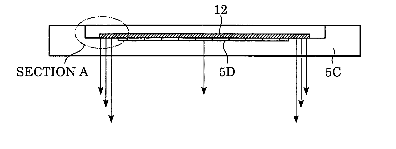
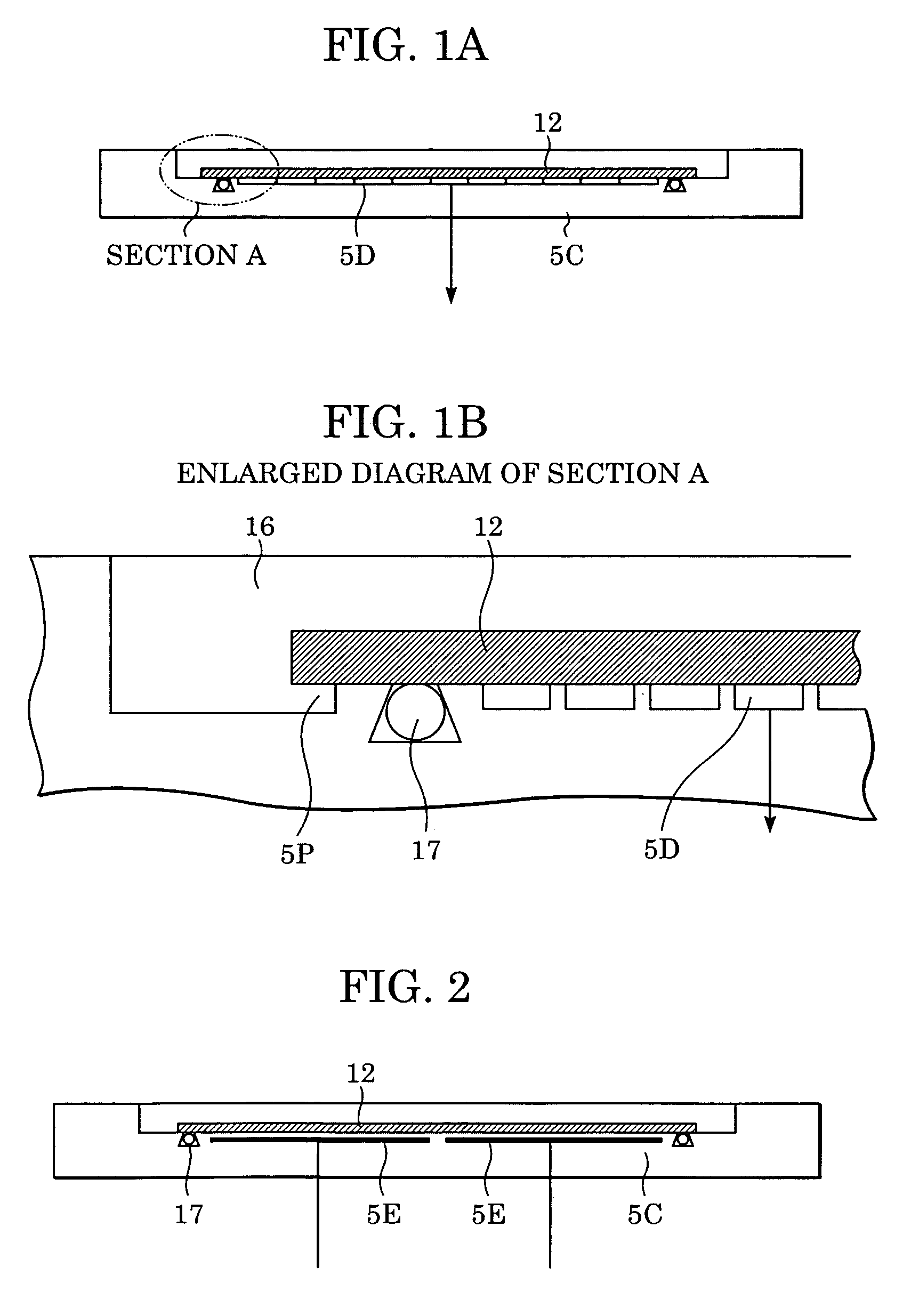
[0041]FIG. 1A illustrates a detachable wafer chuck 5C, i.e. a substrate holder, according to a first embodiment of the present invention. FIG. 1B is an enlarged view of section A in FIG. 1A. The wafer chuck 5C of the first embodiment corresponds to the structure shown in FIG. 12, but is additionally provided with an O-ring sealant 17, i.e. an elastic sealing member, which is in contact with the undersurface of the wafer 12. Specifically, the O-ring sealant 17 is disposed along the periphery of the undersurface of the wafer 12 while being in contact with an inner peripheral portion of the undersurface of the wafer 12.
[0042] A structure for preventing a leakage of immersion liquid to a wafer suction unit will now be described with reference to FIGS. 1A and 1B. In FIGS. 1A and 1B, a vacuum-chuck component 5D provided in the wafer chuck 5C vacuums the wafer 12 so as to fixedly support the wafer 12. As shown in FIG. 1B, the O-ring sealant 17 is disposed adjacent to a circumferential pro...
second embodiment
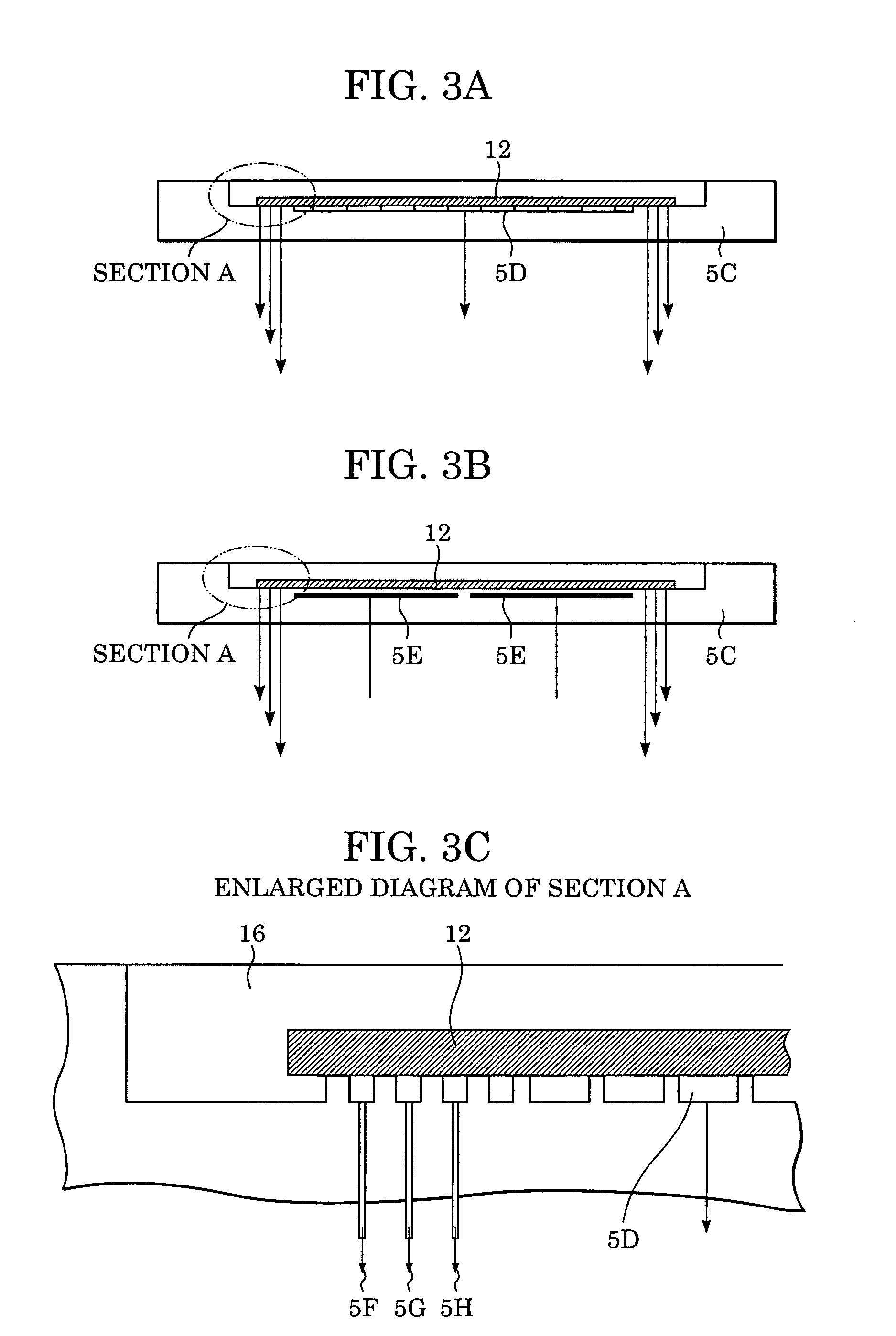
[0045]FIGS. 3A to 3C illustrate a second embodiment of the present invention. In place of the elastic O-ring sealant 17 provided in the first embodiment, the second embodiment is provided with a differential exhaust unit. Specifically, the differential exhaust unit is disposed along a periphery of a wafer-suction surface of the wafer chuck 5C while facing the inner peripheral portion of the undersurface of the wafer 12.
[0046] Referring to FIG. 3C, the differential exhaust unit is disposed along the outermost portion of the vacuum-chuck component 5D in a ring-like manner. The differential exhaust unit includes an exhaust duct A (5F), an exhaust duct B (5G), and an exhaust duct C (5H) which are independent of one another.
[0047] According to the second embodiment, the exhaust duct A (5F) is used for atmospheric pressure, the exhaust duct B (5G) is used for low vacuum pressure (intermediate pressure), and the exhaust duct C (5H) is used for suction-holding pressure. Consequently, by g...
third embodiment
[0049]FIGS. 4A to 4C illustrate a third embodiment of the present invention. In place of the elastic O-ring sealant 17 in the first embodiment, the third embodiment is provided with a liquid-sealant pool disposed along an outer peripheral portion of the wafer chuck 5C.
[0050] Referring to FIG. 4C, a circumferential liquid-sealant groove 5K is disposed around the outer periphery of the vacuum-chuck component 5D. Moreover, a liquid-sealant supplier for supplying a liquid sealant 5J to the liquid-sealant groove 5K is also provided. The liquid sealant 5J should be formed of a material that cannot be easily diffused into the immersion liquid 16 while still having sealability. For this reason, the liquid sealant 5J should be a type of liquid having relatively high viscosity and density. For example, the liquid sealant 5J may be a fluorinated inert refrigerant, fluorinated oil, or a gelatinous polymer material.
[0051]FIG. 4B illustrates an example in which the wafer suction unit according ...
PUM
| Property | Measurement | Unit |
|---|---|---|
| exhaust pressure | aaaaa | aaaaa |
| photosensitive | aaaaa | aaaaa |
| focal depth | aaaaa | aaaaa |
Abstract
Description
Claims
Application Information