Prism sheet, illuminating device, surface emitting device, and liquid crystal display device

Inactive Publication Date: 2005-06-09
ALPS ALPINE CO LTD
View PDF3 Cites 20 Cited by
  • Summary
  • Abstract
  • Description
  • Claims
  • Application Information

AI Technical Summary

Benefits of technology

[0043] According to the above-mentioned structure, the liquid crystal display device is provided with the surface emitting device capable of emitting light having high brightness and excellent brightness uniformity. Therefore, it is possible to obtain bright display without brightness irregularity.
[0044] As described above, the prism sheet of the present invention can refract light having high directivity without dispersion. In addit

Problems solved by technology

However, since the prism sheet has limitations in allowing light components to travel in the same direc

Method used


Image

  • Prism sheet, illuminating device, surface emitting device, and liquid crystal display device
  • Prism sheet, illuminating device, surface emitting device, and liquid crystal display device
  • Prism sheet, illuminating device, surface emitting device, and liquid crystal display device

Examples


first embodiment

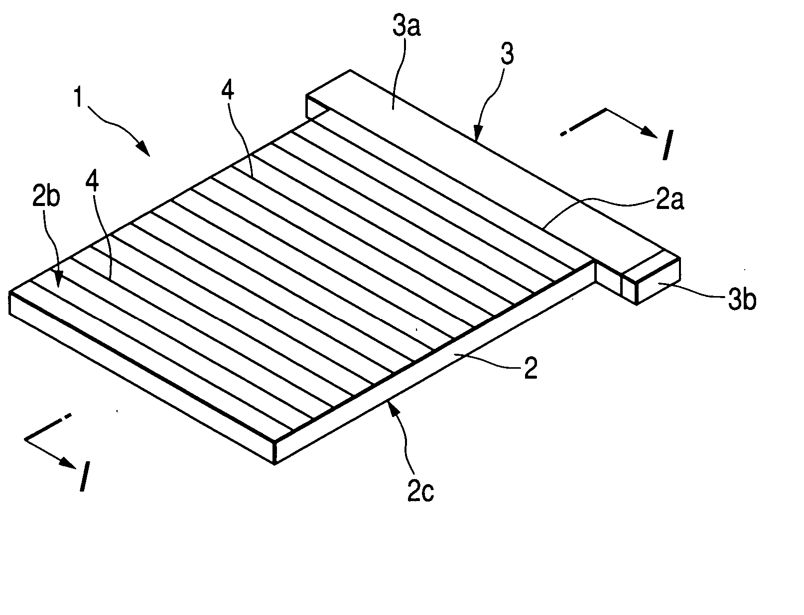
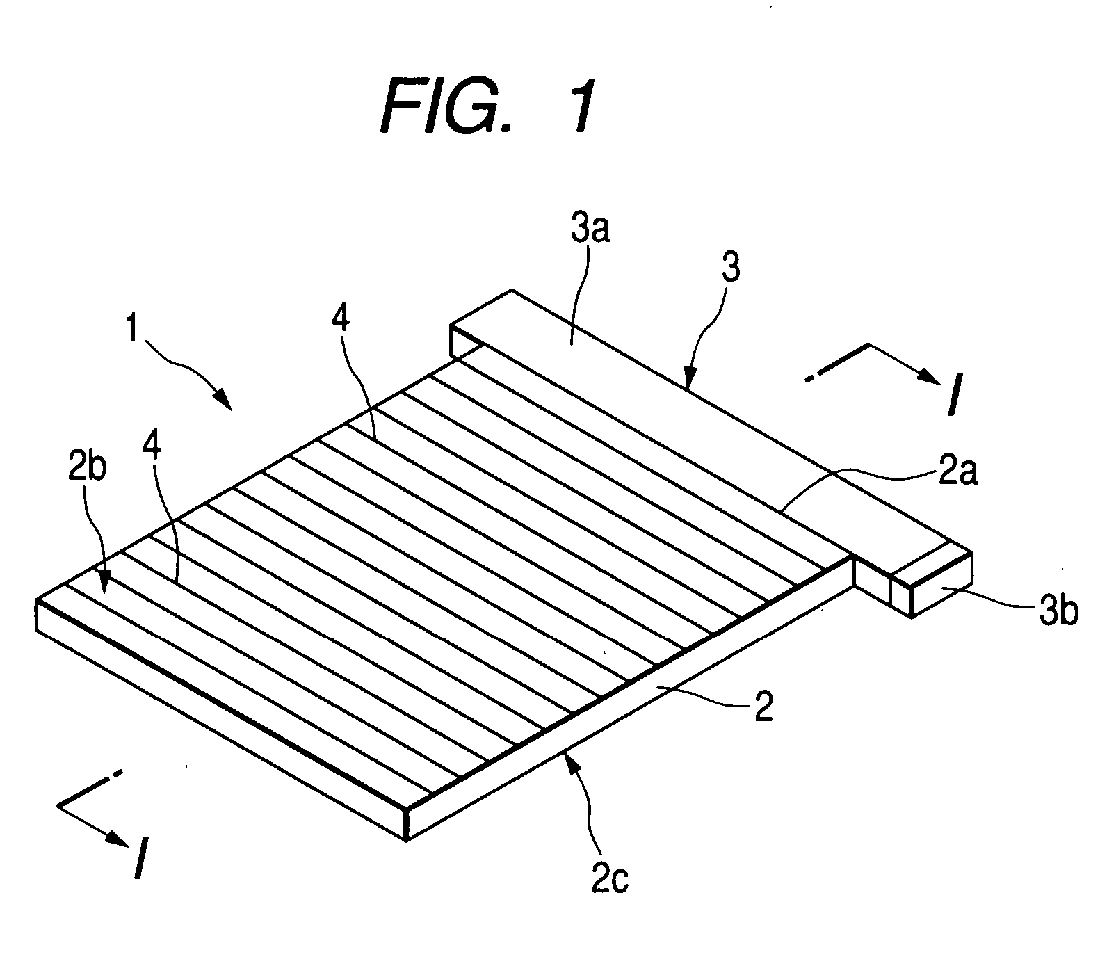
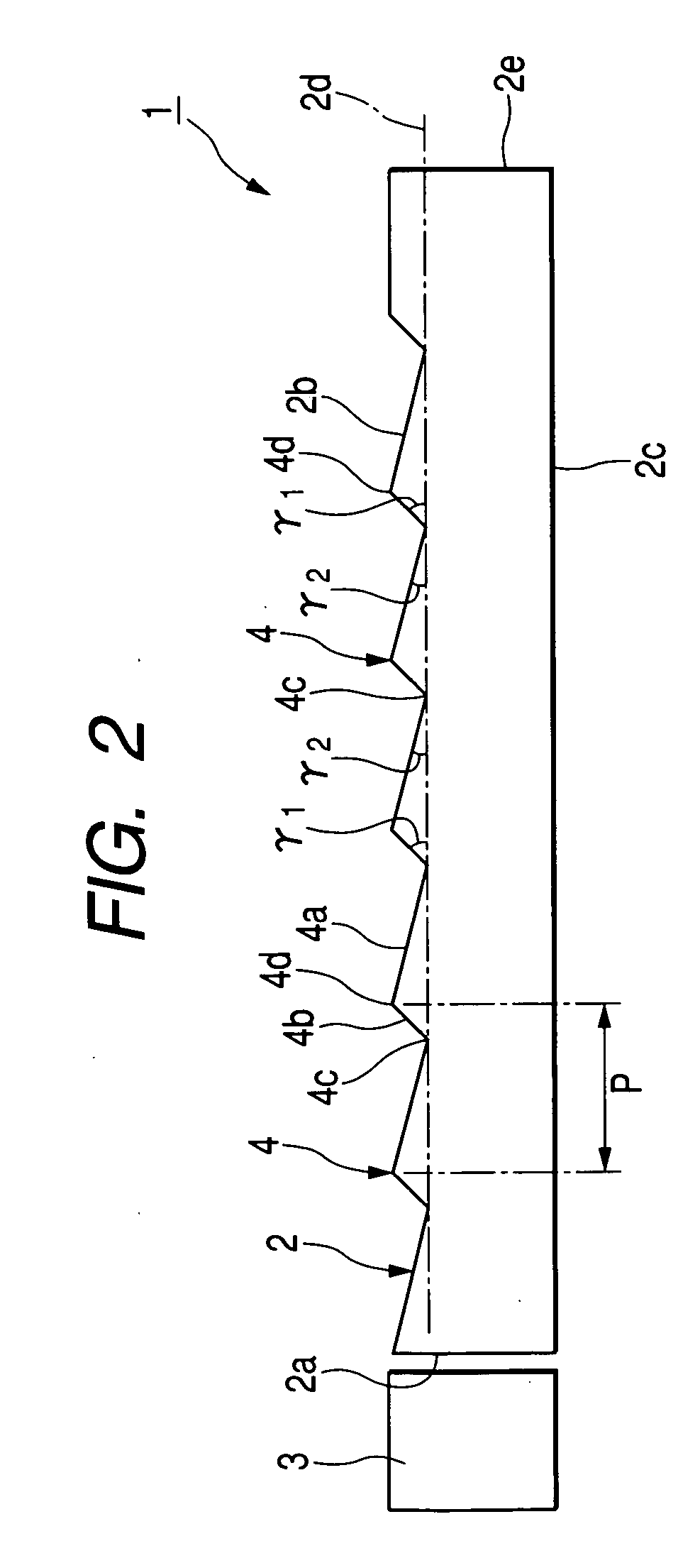
[0063] An illuminating device according to a first embodiment of the present invention will be described with reference to the drawings. FIG. 1 is a perspective view of the illuminating device according to the present embodiment, and FIG. 2 is a cross-sectional view schematically illustrating the illuminating device according to the present embodiment. FIG. 3 is a view schematically illustrating the traveling direction of light introduced into a light guiding plate.

[0064] As shown in FIGS. 1 and 2, an illuminating device 1 mainly comprises a transparent light guiding plate 2 and a light source device (light source) 3. The light source device 3 is provided at the side of one edge 2a of the light guiding plate 2 through which light is introduced. In addition, the light guiding plate 2 is composed of a transparent plate, such as an acrylic resin plate. Light emitted from the light source device 3 provided at the side of the one edge 2a is introduced into the light guiding plate 2 thro...

second embodiment

[0081] Next, a second embodiment of the present invention will be described with reference to the drawings. FIG. 6 is a cross-sectional view schematically illustrating an illuminating device of the present embodiment, and FIG. 7 is a schematic view illustrating the traveling direction of light introduced into the light guiding plate. In the illuminating device of the present embodiment shown in FIGS. 6 and 7, the same components as those in the first embodiment have the same reference numerals, and a description thereof will be omitted for simplicity of explanation.

[0082] As shown in FIG. 6, an illuminating device 11 comprises a transparent light guiding plate 2, the light source device (light source) 3, and a reflective plate 7 mounted on the light guiding plate 2. The light source device 3 is provided at the side of the one edge 2a of the light guiding plate 2 into which light is introduced. In addition, the light guiding plate 2 is composed of a transparent plate, such as an acr...

third embodiment

[0091] Next, an illuminating device according to a third embodiment of the present invention will be described with reference to the drawings. FIG. 8 is a cross-sectional view schematically illustrating an illuminating device according to the present embodiment, and FIG. 9 is a view schematically illustrating the traveling direction of light introduced into a light guiding plate. In addition, in the illuminating device of the present embodiment shown in FIGS. 8 and 9, the same components as those in the first embodiment have the same reference numerals, and a description thereof will be omitted for simplicity of explanation.

[0092] As shown in FIG. 8, an illuminating device 21 comprises a transparent light guiding plate 22 and the light source device (light source) 3. The light source device 3 is provided at the side of one edge 22a of the light guiding plate 22 through which light is introduced. In addition, the light guiding plate 22 is composed of a transparent plate, such as an ...


PUM


Abstract

A surface emitting device includes a light guiding plate, a light source, and a prism sheet. The light guiding plate is provided with prism portions each having a slight inclined plane and a steep inclined plane arranged closer to one edge than the slight inclined plane. A plurality of light refracting portions each having a refractive surface and a reflective surface are provided on an incident surface of the prism sheet. Light introduced into the light guiding plate from the light source is emitted from the slight inclined plane and is then incident on the light refracting portion. The light is introduced into the prism sheet by the refracting surface and is then reflected from the reflective surface to be emitted.

Description

BACKGROUND OF THE INVENTION [0001] 1. Field of the Invention [0002] The present invention relates to a prism sheet, an illuminating device, a surface emitting device, and a liquid crystal display device. [0003] 2. Description of the Related Art [0004] Conventionally, a backlight device, which is a kind of surface emitting device, for emitting light from the rear side of a liquid crystal display panel to a display surface has been commonly used as an illuminating means of the liquid crystal display device. In general, the conventional backlight device includes a light guiding plate composed of a transparent resin plate having one edge, an emission surface orthogonal to the one edge, and a prism surface provided opposite to the emission surface; a light source arranged at the side of the one edge of the light guiding plate; a prism sheet arranged at the side of the emission surface of the light guiding plate. [0005] In the conventional backlight device, light emitted from the light so...

Claims


Application Information

Patent Timeline
IPC IPC(8): G02B6/00F21V8/00F21Y101/02G02B5/02G02B5/04G02F1/13357
CPCG02B6/0038G02B6/0063G02B6/0055G02B6/0053G02F1/1335
Inventor SUGIURA, TAKURO
Owner ALPS ALPINE CO LTD
Why Eureka
Try Eureka