Developing apparatus and electrostatic recording apparatus using the same

a technology of electrostatic recording and developing apparatus, applied in the direction of electrographic process apparatus, instruments, optics, etc., to achieve the effects of stable concentration of toner, low cost, and fast printing speed

Inactive Publication Date: 2005-06-09
RICOH PRINTING SYST
View PDF6 Cites 10 Cited by
  • Summary
  • Abstract
  • Description
  • Claims
  • Application Information

AI Technical Summary

Benefits of technology

[0045] In the invention, the concentration of the toner of the developing apparatus using a two components developer can be controlled to a specified value and therefore, there can be provided a small-sized low cost developing apparatus without a drawback that when the toner is supplied, the concentration of the toner of the developer passing the supply portion becomes excessive to scatter the toner from the developing apparatus, or fogging is brought about in a printed image, and capable of dealing with a condition of a large amount of consuming the toner when a print width is wide

Problems solved by technology

However, according to the system, the system of the prior art of comparing an output value of a single toner concentration sensor with a reference toner concentration value and changing a toner amount to be supplied by a difference therebetween is added with an effect of correcting a supply amount when the supply amount is varied from an inherent supply amount, and there is not sufficiently resolved the proble

Method used


Image

  • Developing apparatus and electrostatic recording apparatus using the same
  • Developing apparatus and electrostatic recording apparatus using the same
  • Developing apparatus and electrostatic recording apparatus using the same

Examples


example 1

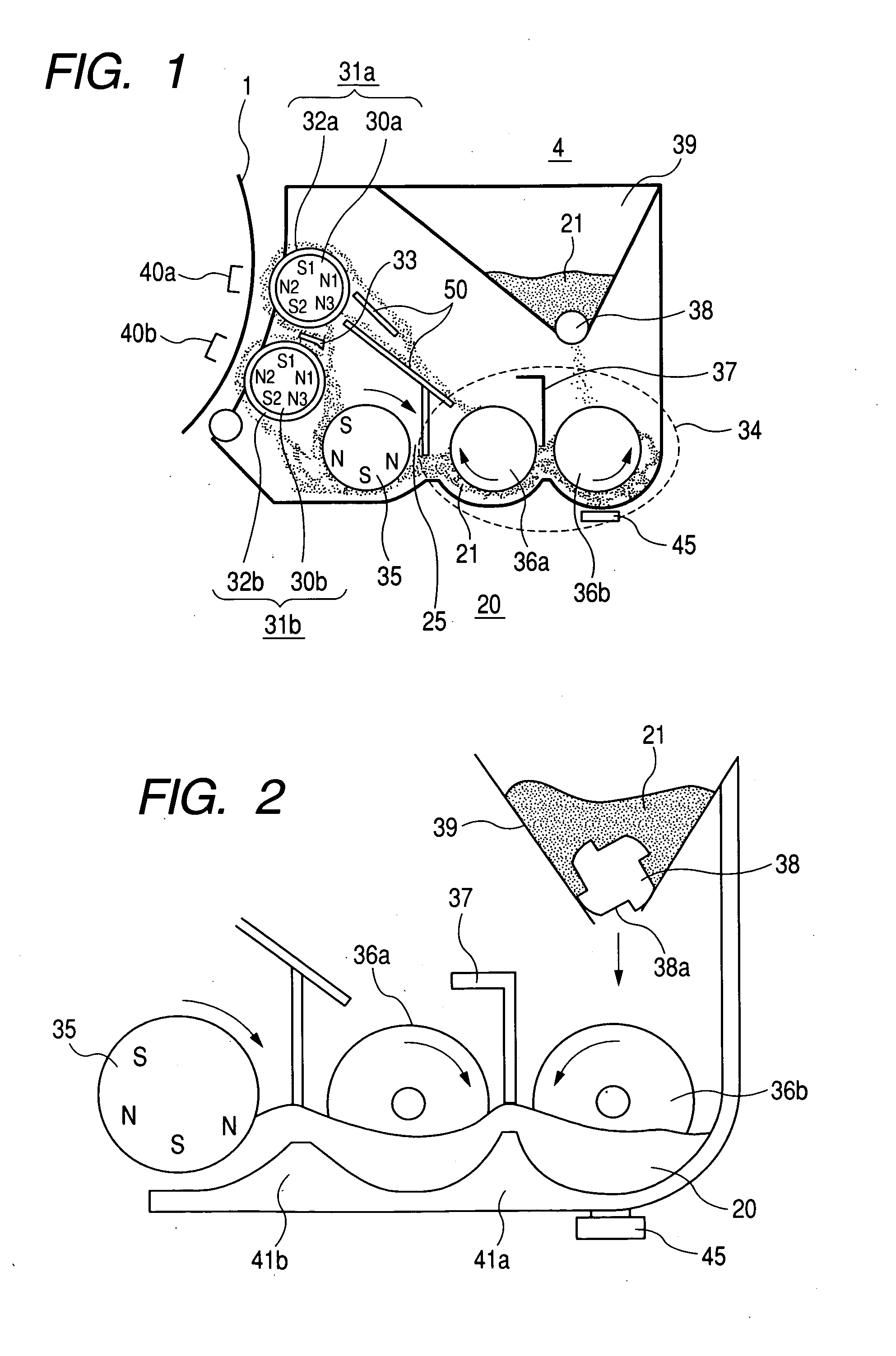
[0082] As shown by FIG. 1, inside of the developing apparatus 4 is arranged with two pieces of the developing rollers 31a, 31b having a diameter of 50 mm and thermally sprayed with SUS at a surface thereof having the rotatable sleeve rollers 32a, 32b at the outer peripheries of the fixed magnets 30a, 30b by interposing the carrying amount restricting member 33 therebetween.

[0083] At the developing roller 31a arranged on the upstream side in the rotational direction of the photosensitive member 1, the sleeve roller 32a is rotated in the clockwise direction, that is, the developer 20 is inversely rotated at the developing region 40a, and at the developing roller 31b arranged on the downstream side of the rotational direction of the photosensitive member 1, the sleeve roller 32b is rotated in the counterclockwise direction, that is, rotated regularly at the developing region 40b.

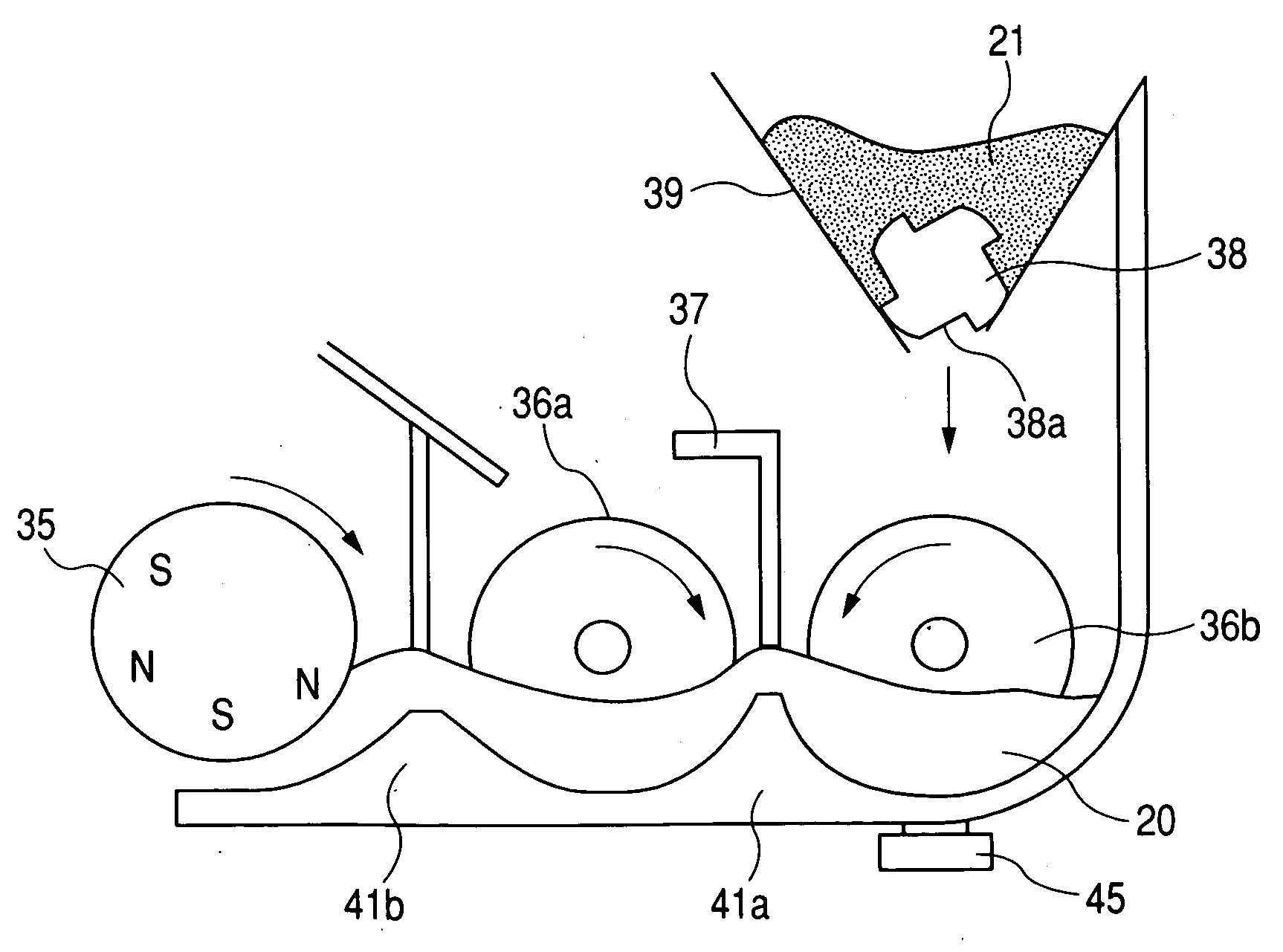
[0084] A vicinity of the developing roller 31b is arranged with the carry roller 35 having a diameter of 5...

example 2

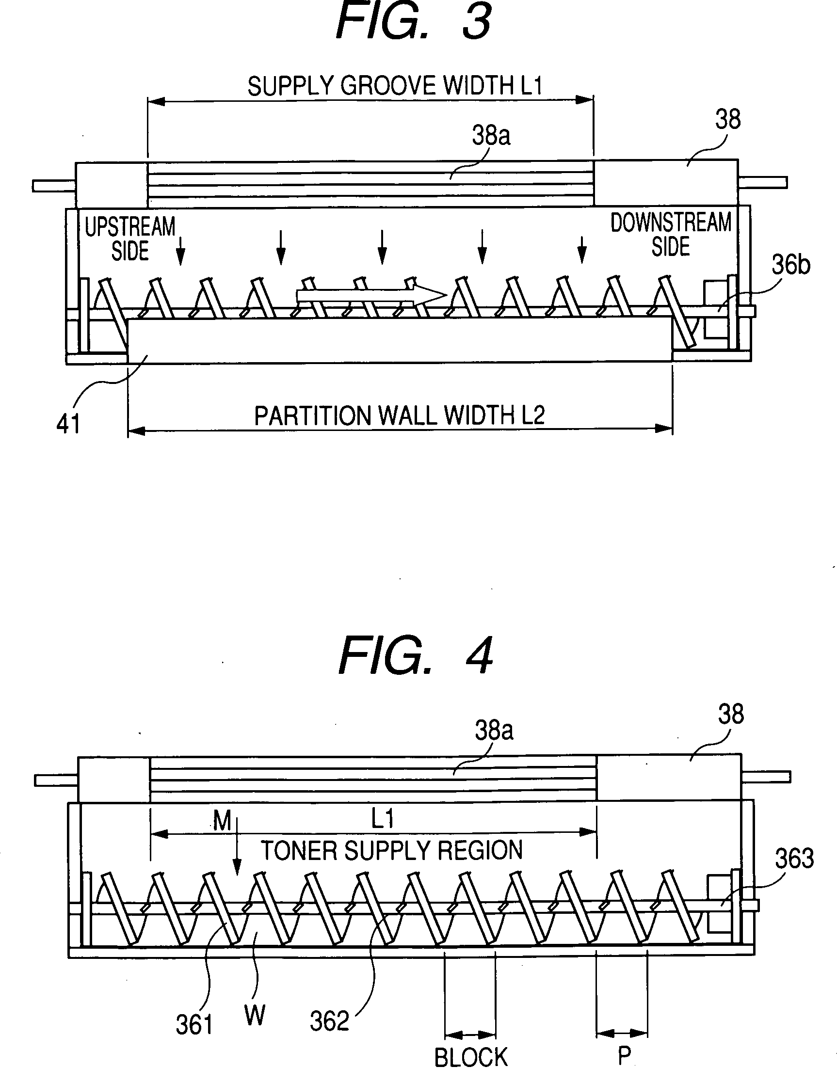
[0099] This is an example of setting the pitch of the auger 36b to 24 mm and otherwise, the example is the same as Example 1.

[0100] According to the example, the toner concentration at the outlet portion of the auger 36b is 5.86% to be lower than the mixing limit toner concentration, further, the flow rate of the toner 21 included in the developer 20 and carried from the auger 36b is increased from 3.55 (g / s) of Example 1 to 4.17 (g / s). As a result, the toner concentration at inside of the developing apparatus 4 can be made to be equal to or larger than the specified value more fastly to be able to deal with printing consuming a larger amount of the toner. In the case of the example, the value of (W×(Tc / 100)+M) / (W+M) of Equation (1), mentioned above, becomes 0.0586 (the toner concentration at the outlet portion of the auger 36 after having been supplied with toner is 5.86%) and is designed to be smaller than 0.0600 of Tmax / 100.

example 3

[0101] This is an example of increasing the amount of the developer at the portion of the auger 36b. By increasing the developer amount at the auger portion to 1000 g, despite conditions similar to those of Comparative Example 2 otherwise, the toner concentration at the outlet portion of the auger 36b is 5.99% to be improved equivalent to Example 1, further, the flow rate of the toner 21 included in the developer 20 and carried from the auger 36b is 3.55 (g / s) to be improved equivalent to Example 1. The value of (W×(Tc / 100)+M) / (W+M) of Equation (1), mentioned above, becomes 0.0599 (the toner concentration at the outlet portion of the auger 36b after having been supplied with the toner becomes 5.99%) and is designed to be smaller than 0.0600 of Tmax / 100.


PUM


Abstract

A developing apparatus characterized in being constituted to satisfy Equation (1) shown below when an amount of a developer carried by 1 pitch of a carrying member of an auger or the like is designated by notation W(g), a toner amount supplied by 1 pitch during a time period in which the developer carried by 1 pitch passes a supply region of a toner supply roller is designated by notation M(g), a toner concentration of the developer detected by a toner concentration sensor is designated by notation Tc (%), and a mixing limit toner concentration is designated by notation Tmax (%).
(W×(Tc/100)+M)/(W+M)≦Tmax/100   (1)

Description

BACKGROUND OF THE INVENTION [0001] 1. Field of the invention [0002] The present invention relates to an electrostatic recording apparatus of a printer, a copier or the like using an electrophotography system, particularly relates to a developing apparatus using a two components developer and an electrostatic recording apparatus using the same. [0003] 2. Description of the Related Art [0004]FIG. 8 is an outline view of an electrostatic recording apparatus of an electrophotography system using a developing apparatus of a background art. A developing apparatus 4 includes two developing rollers 31a, 31b at positions opposed to a photosensitive member 1, a carry roller 35 for carrying a developer which is a mixture of a toner 21 and a carrier to the developing rollers 31b, and a carrying amount restricting member 33 for restricting an amount of carrying the developer to a predetermined amount. [0005] An electrostatic latent image formed on the photosensitive member 1 by charging uniforml...

Claims


Application Information

Patent Timeline
IPC IPC(8): G03G15/08
CPCG03G2215/0609G03G2215/0827G03G15/0893G03G15/0853G03G15/0849
Inventor MABUCHI, HIROYUKI
Owner RICOH PRINTING SYST
Why Eureka
Try Eureka