
Device for sealing a cervical canal

a technology for sealing devices and cervical canals, applied in the field of devices for sealing cervical canals, can solve problems such as inability to determine the amount of fluid or gas used in the procedure, loss of pressure,

Inactive Publication Date: 2005-06-09
NADY NADY E
View PDF2 Cites 28 Cited by
  • Summary
  • Abstract
  • Description
  • Claims
  • Application Information

AI Technical Summary

Benefits of technology

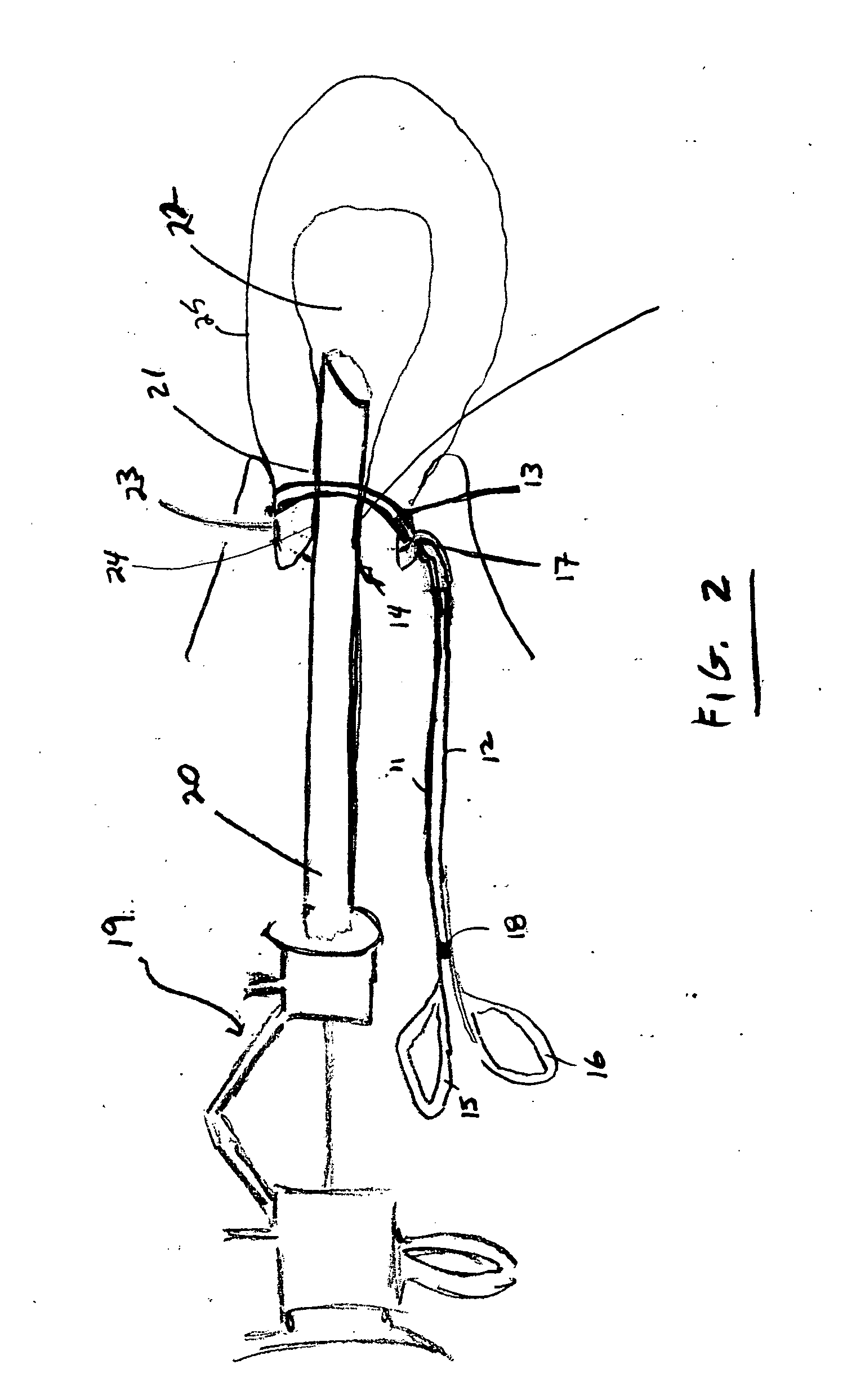
[0009] The present invention provides a device for gripping the exterior of a cervical canal to press the cervical canal inwardly against a tubular portion of a hysteroscope instrument inserted through the cervical canal to resist backflow of fluid or gas used as a distension media within a uterus from flowing out of the cervical canal during the use of the hysteroscope instrument. The device includes a pair of pivotally connected cross arms having forward end portions with curved clamping tips a...

Problems solved by technology

However, the fluid or gas received in the uterus during either diagnostic or surgical hysteroscopy can subsequently flow from the uterus through the cervical canal resulting in a loss of pressure and an incapability of determining the amount of fluid or gas used in the procedure.

Method used


Image

  • Device for sealing a cervical canal
  • Device for sealing a cervical canal
  • Device for sealing a cervical canal

Examples


Embodiment Construction

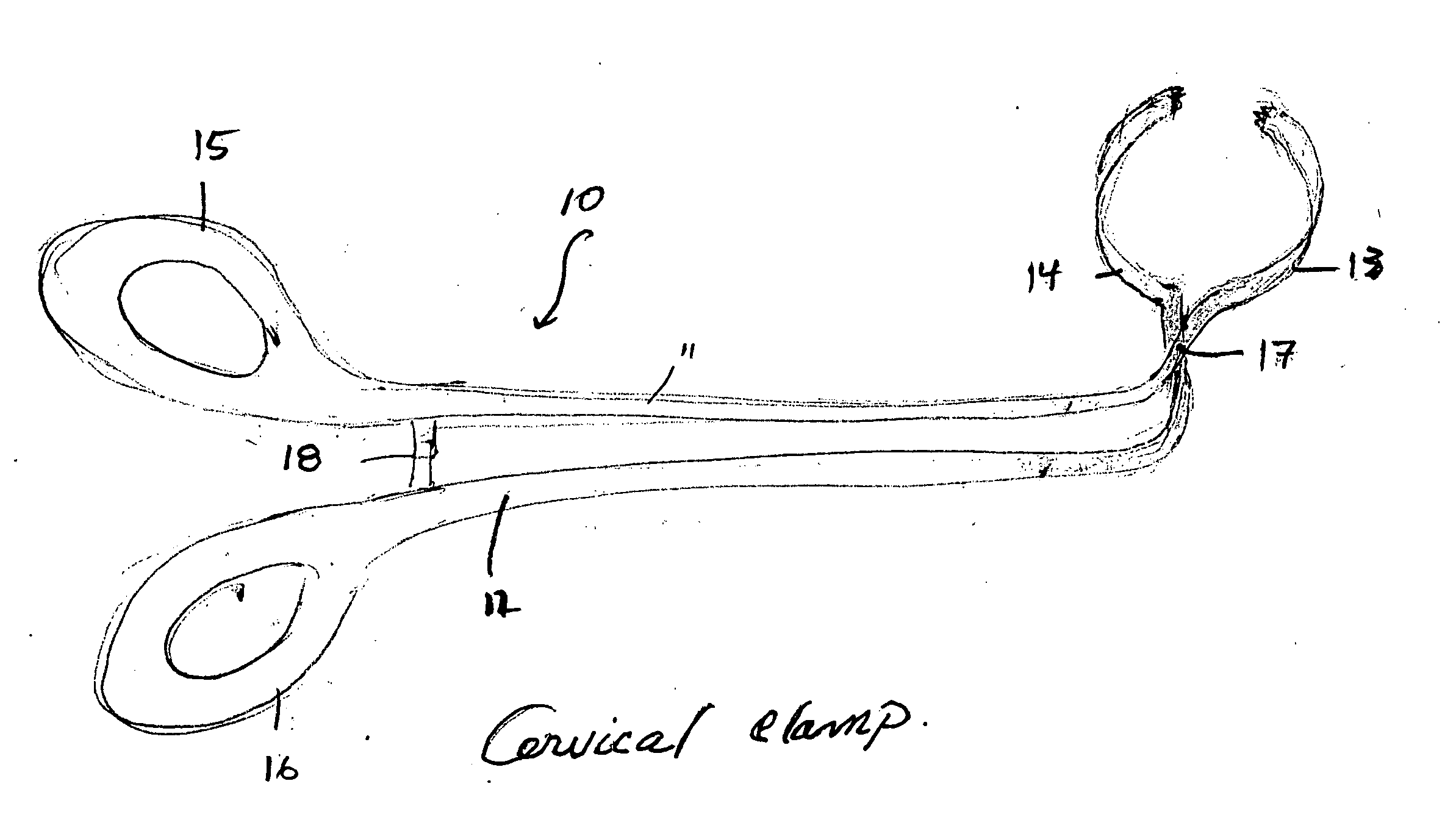
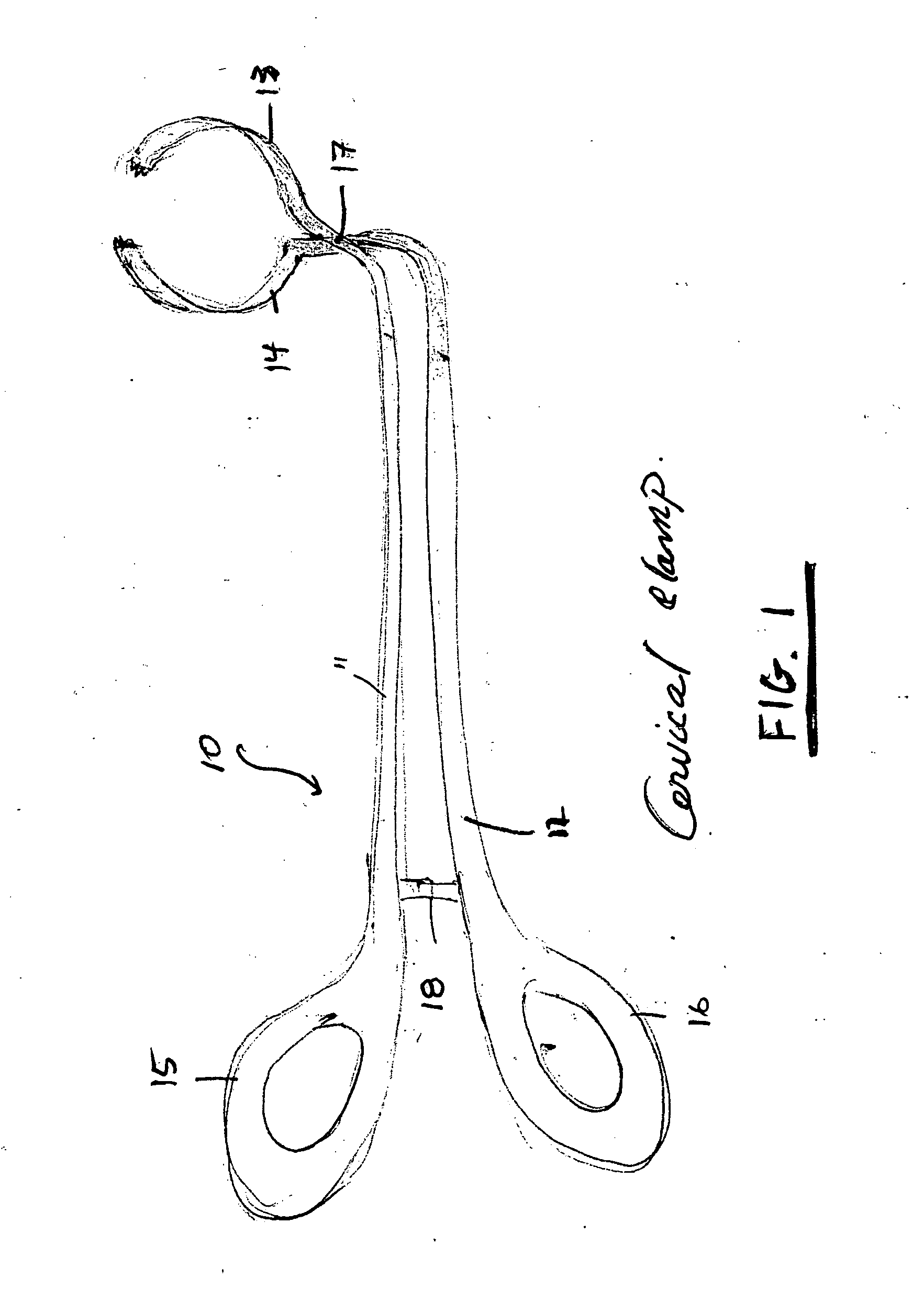
[0017] Referring to the drawings wherein like reference numerals identify similar or like elements throughout the several views and initially to FIG. 1 there is shown the present invention, device 10. Device 10 includes cross arms 11 and 12 which are of narrow elongate construction. Cross arms 11 and 12 have curved clamping tips 13 and 14 at one end and hand-grips 15 and 16 at the opposite end. While the curved clamping tips 13 and 14 are shown with a generally circular shape an oval and other curved shapes can also be used. Curved clamping tips 13 and 14 are aligned at an angle relative to hand-grips 15 and 16. The angle of alignment while shown at approximately 90 degrees can range from approximately 45 degrees to approximately 135 degrees.

[0018] Cross arms 11 and 12 are pivotally connected to each other with connection 17. The closing of hand-grips 15 and 16 (i.e. bringing hand-grip 15 toward hand-grip 16) enables curved clamping tips 13 and 14 to be brought toward one another a...


PUM


Abstract

A device useful in forming a seal between a hysteroscope instrument and a cervical canal during diagnostic or surgical procedures known as hysteroscopy. The device grasps the exterior of the cervical canal pressing the cervical canal inwardly toward the outer surface of the hysteroscope instrument forming a seal between the outer surface of the hysteroscope instrument and the cervical canal, thereby preventing fluid or gas from exiting the cervical canal.

Description

BACKGROUND OF THE INVENTION [0001] 1. Field of the Invention [0002] The present invention relates to a device useful in forming a seal between a hysteroscope instrument and a cervical canal during diagnostic or surgical procedures known as hysteroscopy. The device grasps the exterior of the cervical canal pressing the cervical canal inwardly toward the outer surface of the hysteroscope instrument forming a seal between the outer surface of the hysteroscope instrument and the cervical canal, thereby preventing fluid or gas from exiting the cervical canal. [0003] 2. Related Art [0004] Procedures which require entry into the uterus are well known. Two such procedures are diagnostic and surgical hysteroscopy. [0005] Diagnostic hysteroscopy is a procedure used to help diagnose abnormal uterine bleeding, infertility, uterine and cervical cancer, location of intra uterine devices, complicated abortion and fetal examination. Diagnostic hysteroscopy involves inserting a hysteroscope instrume...

Claims


Application Information

Patent Timeline
IPC IPC(8): A61B17/132A61B17/28A61B17/34A61B17/42A61F6/08
CPCA61B17/1322A61B17/3474A61B17/42A61F6/08A61B2017/2946A61B2017/4225A61B2017/2926
Inventor NADY, NADY E.
Owner NADY NADY E
Learn More