Ladder and safety device therefor

a safety device and ladder technology, applied in the field of ladders, can solve the problems of people falling off the ladder, and falling off, and achieve the effect of reducing the chance of falling o

Inactive Publication Date: 2005-06-16
TILLEY JACK
View PDF6 Cites 13 Cited by
  • Summary
  • Abstract
  • Description
  • Claims
  • Application Information

AI Technical Summary

Benefits of technology

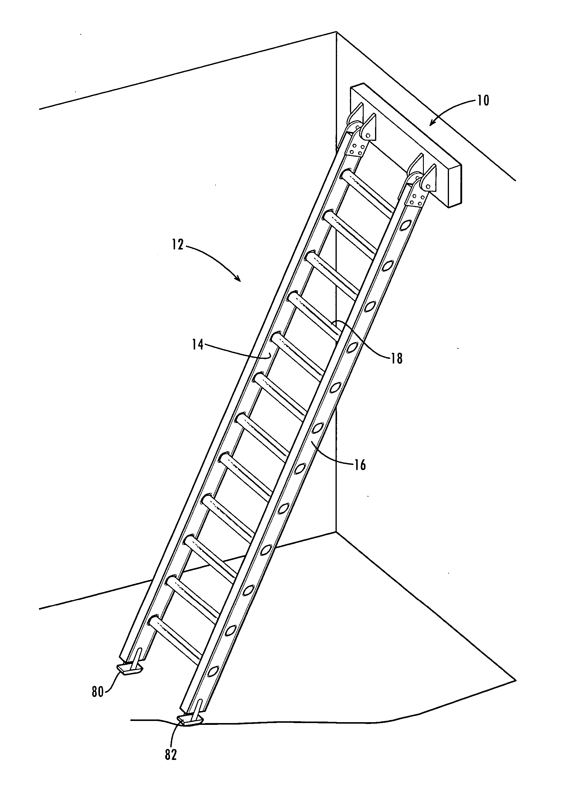
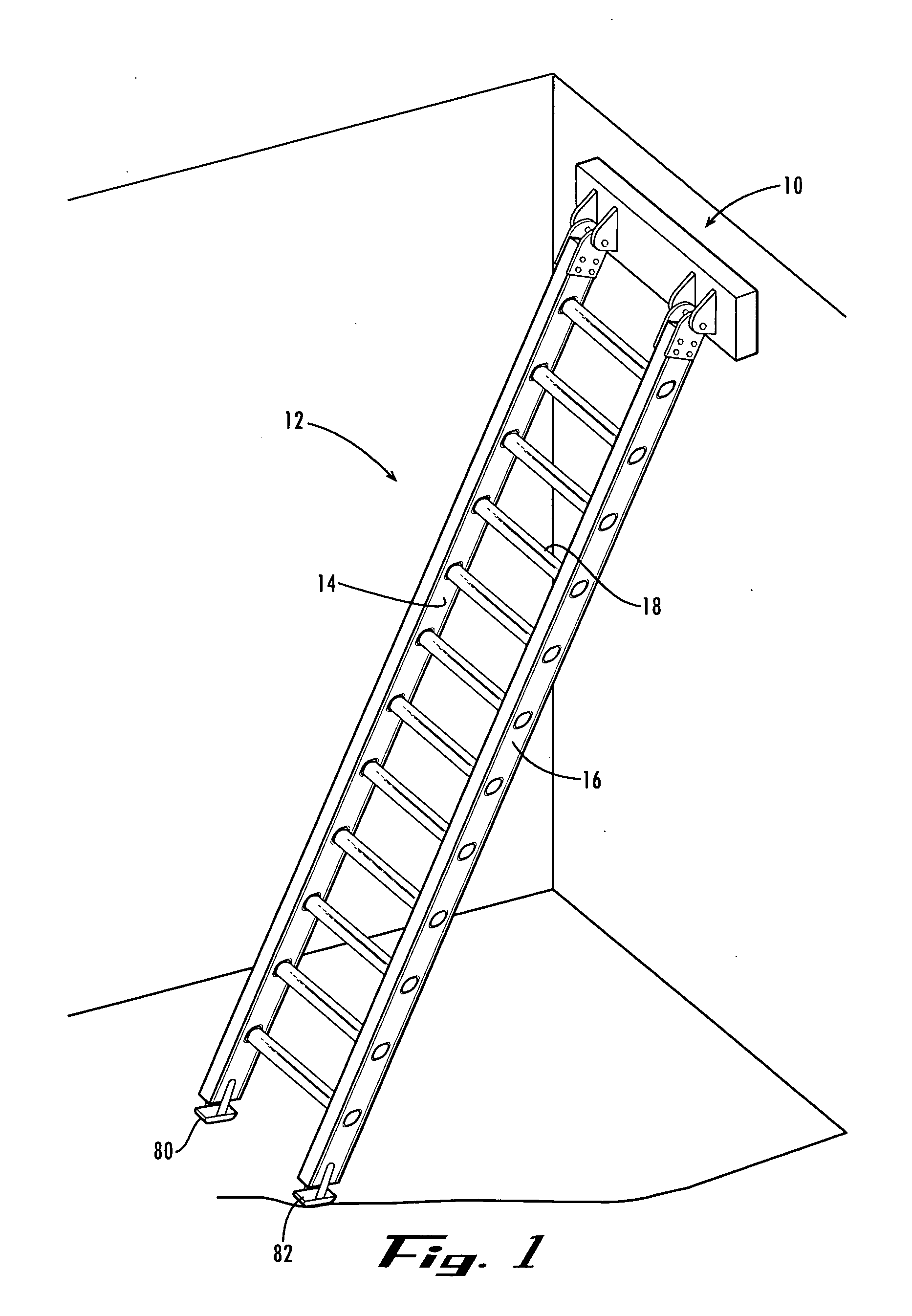
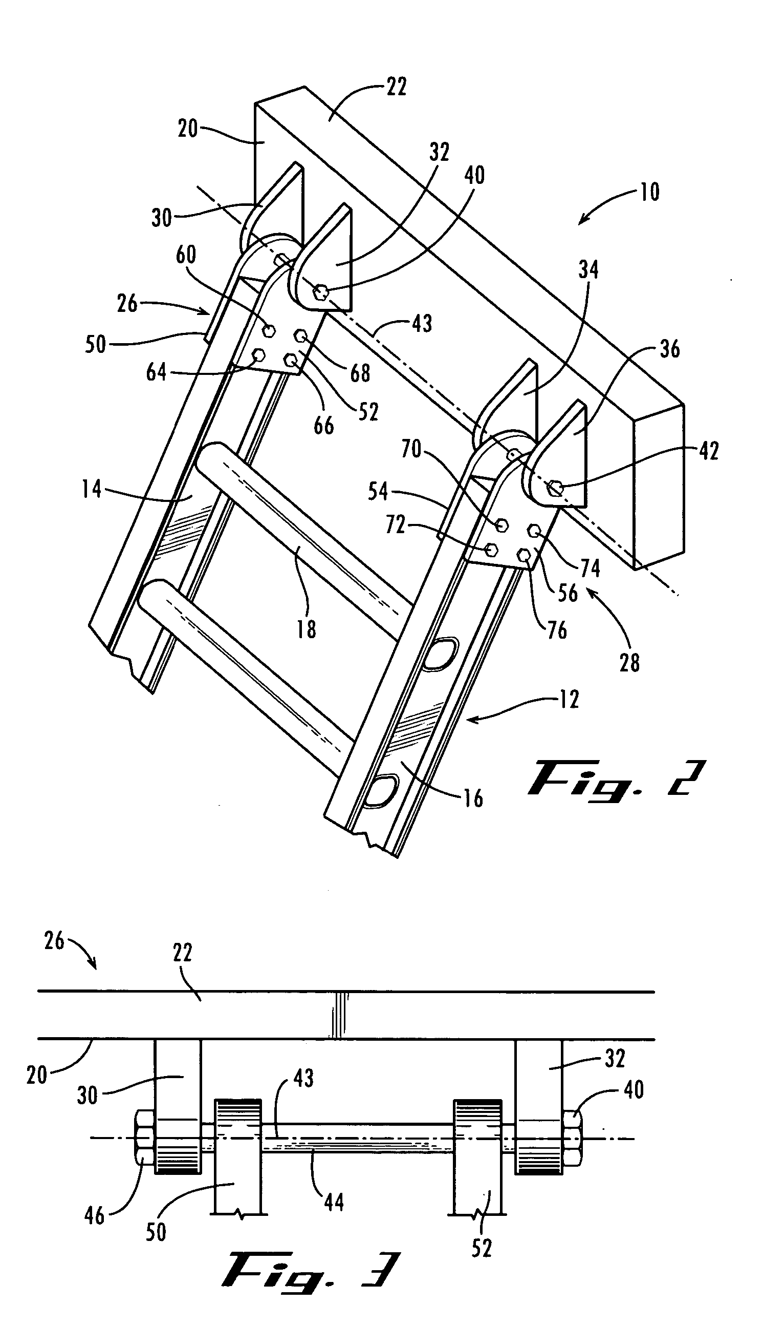
[0009] In another form, the present invention comprises a safety device for use with an extension ladder of the type having a pair of parallel side rails having top ends and bottom ends. The safety device is provided to minimize slippage between the extension ladder and a building, wall or other structure having an upright surface. The safety device includes a pivot member pivotally secured adjacent the top ends of the rails and having a resilient face plate for engaging the upright surface. Preferably, the pivot member further includes a mounting assembly for mounting the pivot member to the tops of the rails. The mounting assembly further includes a rail bolster for coupling the safety device to the ladder.

Problems solved by technology

However, the plastic pieces offer little grip to keep the ladder from slipping sideways.
If the person on the ladder extends himself or herself too far off the center of the ladder, the ladder can slide laterally off the wall, which in turn can cause the person to fall off the ladder and incur a serious injury.
Although these devices help to stabilize the ladder, they also tend to make moving the ladder from point to point around the house more difficult, as well as to make transporting and storing the ladder, on a truck or at home, more difficult.
Although the foam helps to protect the side of the house, the duct tape offers little resistance to a sideways skid of the ladder if the user reaches too far off the center of the ladder.

Method used


Image

  • Ladder and safety device therefor
  • Ladder and safety device therefor
  • Ladder and safety device therefor

Examples


Embodiment Construction

[0016] The present invention may be understood more readily by reference to the following detailed description of the invention taken in conjunction with the accompanying drawing figures, which form a part of this disclosure. It is to be understood that this invention is not limited to the specific devices, methods, conditions or parameters described and / or shown herein, and that the terminology used herein is for the purpose of describing particular embodiments by way of example only and is not intended to be limiting of the claimed invention. Also, as used in the specification including the appended claims, the singular forms “a,”“an,” and “the” include the plural, and reference to a particular numerical value includes at least that particular value, unless the context clearly dictates otherwise. Ranges may be expressed herein as from “about” or “approximately” one particular value and / or to “about” or “approximately” another particular value. When such a range is expressed, anoth...


PUM


Abstract

An apparatus for use against a building, wall or the like structure having an upright surface including a ladder having a pair of parallel side rails with top ends and bottom ends and a plurality of rungs extending therebetween and a stabilizing device secured adjacent the top ends of the rails of the ladder for engaging the upright surface. The stabilizing device has a pivot member pivotally mounted to the rails for pivotal motion relative to the rails and a resilient face for engaging the upright surface and to help resist slipping. The pivot member allows the resilient face to confront the upright surface over a range of angular orientations of the rails relative to the upright surface. Preferably, the resilient face has a non-marring and slip resistant surface for engaging the upright surface.

Description

CROSS-REFERENCE TO RELATED APPLICATIONS [0001] The present application claims the priority benefit of U.S. provisional patent application Ser. No. 60 / 528,309, filed Dec. 10, 2003 and incorporates the disclosure of the same herein by reference.FIELD OF THE INVENTION [0002] The present invention relates generally to the field of ladders and more particularly to a safety device for a ladder. BACKGROUND OF THE INVENTION [0003] Many ladders manufactured today have a plastic piece attached to the top of each rail to rest against a wall (or a side of a house) to protect the wall. However, the plastic pieces offer little grip to keep the ladder from slipping sideways. If the person on the ladder extends himself or herself too far off the center of the ladder, the ladder can slide laterally off the wall, which in turn can cause the person to fall off the ladder and incur a serious injury. [0004] To prevent the ladder from sliding off the wall, some ladders incorporate stabilizing devices att...

Claims


Application Information

Patent Timeline
Patent Type & Authority Applications(United States)
IPC IPC(8): E06C7/48
CPCE06C7/48
Inventor TILLEY, JACK
Owner TILLEY JACK
Why Eureka
Try Eureka