Eureka AIR delivers breakthrough ideas for toughest innovation challenges, trusted by R&D personnel around the world.

Shear-Layer Chuck for Lithographic Apparatus

a chuck and lithographic technology, applied in the field of lithographic apparatus, can solve the problems of chuck as well as the object deformation, uniform transfer of acceleration-induced stress from the stage to the chuck (as well as from the chuck to the object), and the potential for slippage between the chuck and the object, so as to achieve the effect of minimizing the slippage of a supported obj

Inactive Publication Date: 2011-01-20
ASML HLDG NV
View PDF6 Cites 6 Cited by
  • Summary
  • Abstract
  • Description
  • Claims
  • Application Information

AI Technical Summary

Benefits of technology

The present invention provides a chuck that minimizes slippage of an object under stress while still providing a desired shear compliance. This is achieved by using an array of elongated elements that render a uniform transfer of stress between the chuck and the stage, resulting in a reduced likelihood of object slippage during movement of the chuck. The elongated elements are normal to the chuck and the stage, and their first ends contact the chuck and their second ends contact the stage. The elongated elements can be used in a lithographic apparatus to support and hold an object during a patterning process. Additionally, the invention provides a system and method for supporting an object using an interface layer with low stiffness in one direction of translation or rotation with respect to the other directions. Overall, the invention improves the accuracy and stability of the chuck during a patterning process.

Problems solved by technology

When acceleration is imparted to the stage during exposure or pre-exposure alignment, a stress is transferred from the stage to the chuck, and this stress may cause the chuck as well as the object to deform.
Typically the transfer of acceleration-induced stress from the stage to the chuck (as well as from the chuck to the object) is not uniform.
This gives rise to a potential for slip between the chuck and the object, especially in cases where the chuck deformation is large.
Chuck deformation may also be caused by temperature differences between the stage, the chuck, and / or the object, resulting in slippage of the object relative to the chuck.
However, kinematic mounts at a number of discrete locations may not uniformly distribute the transfer of stress.
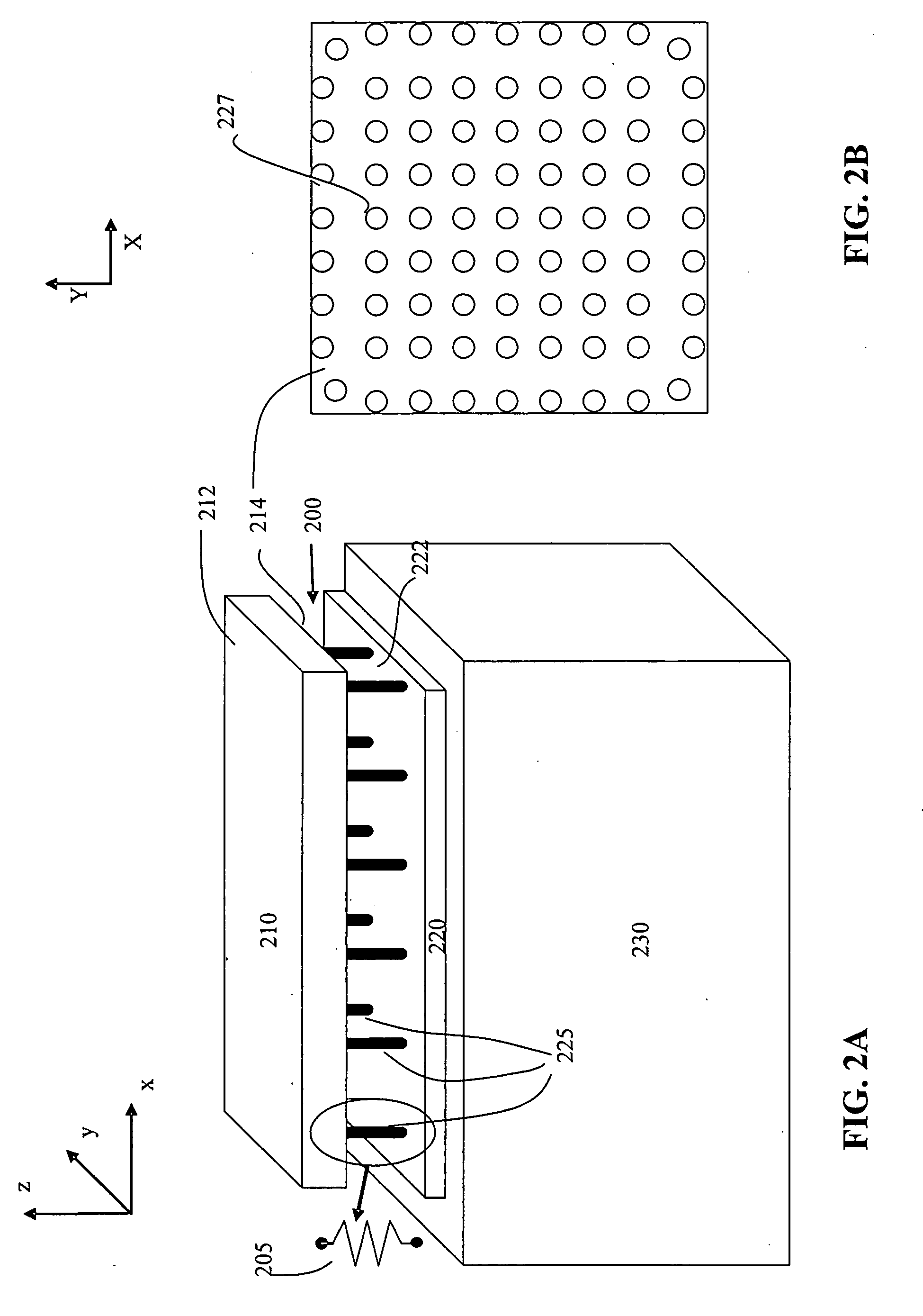
Thus, it may be difficult to tailor burls 225 for a desired shear compliance in all directions of interest.
Burls 225 that directly contact object 210 typically have high compliance in normal direction as well, making it harder to optimize the overall shear compliance of the system.
Moreover, burls 225 with the desired shear compliance are typically long and slender, and their shape makes electrostatic clamping of the object quite challenging.
Additionally, planarity of object 210 may be compromised due to non-uniform stress distribution in burls 225.

Method used


Image

  • Shear-Layer Chuck for Lithographic Apparatus
  • Shear-Layer Chuck for Lithographic Apparatus
  • Shear-Layer Chuck for Lithographic Apparatus

Examples


Embodiment Construction

[0032]This specification discloses one or more embodiments that incorporate the features of this invention. The disclosed embodiment(s) merely exemplify the invention. The scope of the invention is not limited to the disclosed embodiment(s). The invention is defined by the claims appended hereto.

[0033]The embodiment(s) described, and references in the specification to “one embodiment”, “an embodiment”, “an example embodiment”, etc., indicate that the embodiment(s) described can include a particular feature, structure, or characteristic, but every embodiment cannot necessarily include the particular feature, structure, or characteristic. Moreover, such phrases are not necessarily referring to the same embodiment. Further, when a particular feature, structure, or characteristic is described in connection with an embodiment, it is understood that it is within the knowledge of one skilled in the art to effect such feature, structure, or characteristic in connection with other embodiment...


PUM


Abstract

A lithographic apparatus is described that comprises a support structure (300) to hold an object (210). The object may be a patterning device or a substrate to be exposed. The support structure comprises a chuck (321), on which the object is supported, and an array of shear-compliant elongated elements (325) normal to the chuck and the stage (230), such that first ends of the elongated elements contact a surface of the chuck and second ends of the elongated elements contact a stage. Through using the array of elongated elements, a transfer of stress between the stage and the chuck is substantially uniform, resulting in minimization of slippage of the object relative to the surface of the chuck during a deformation of the chuck due to the stress.

Description

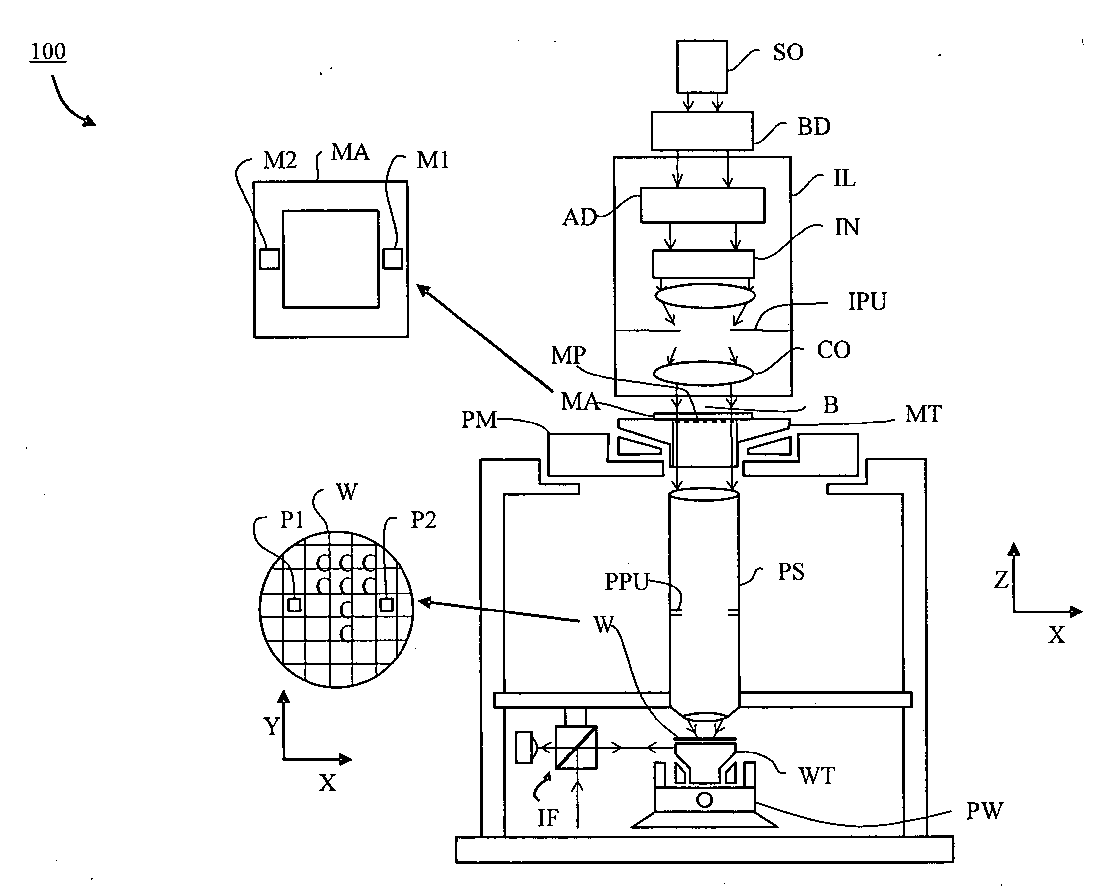
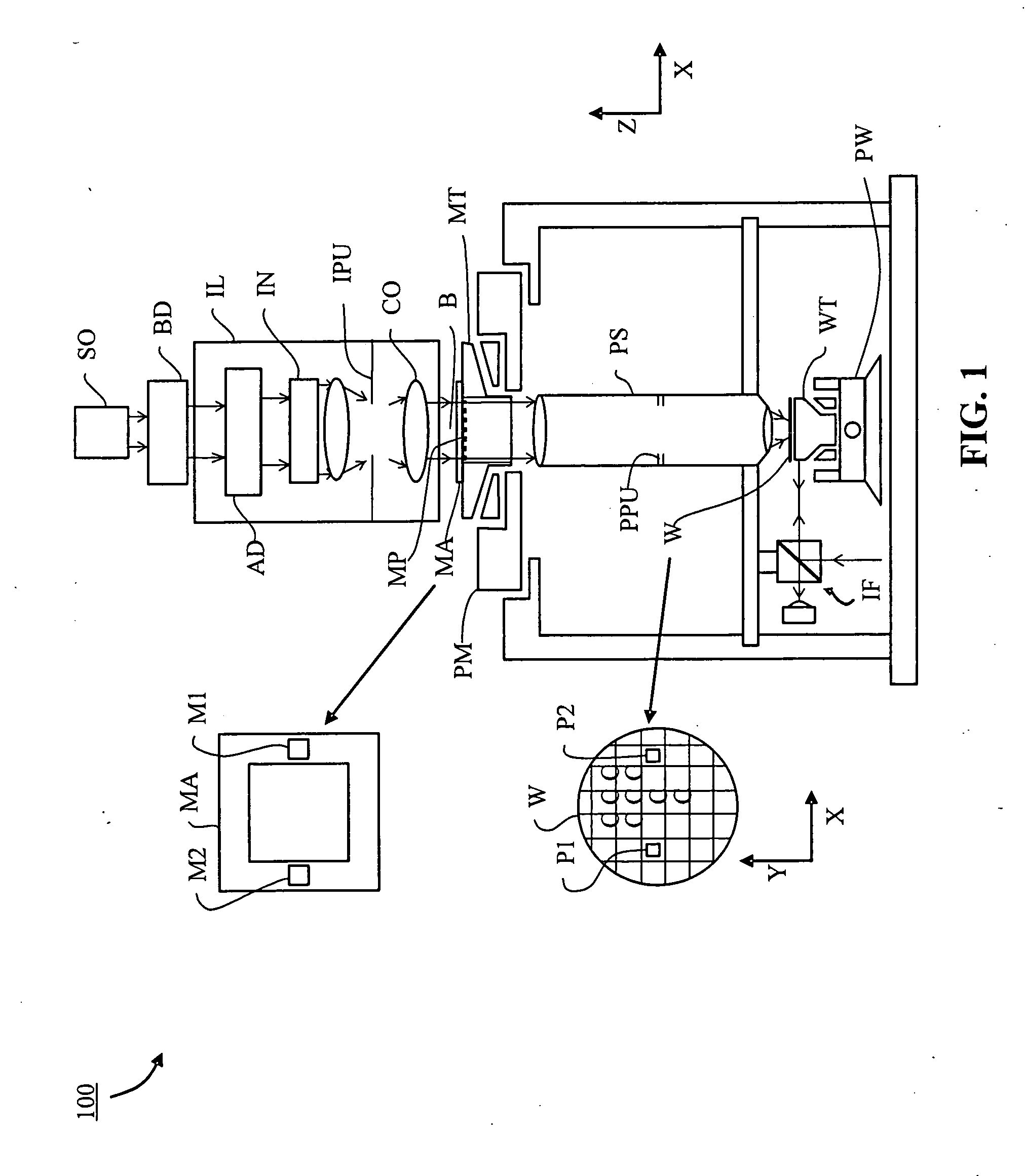
BACKGROUND[0001]1. Field of the Invention[0002]The present invention relates to a lithographic apparatus and method of securely holding an object in the lithographic apparatus.[0003]2. Related Art[0004]A lithographic apparatus is a machine that applies a desired pattern onto a substrate, usually onto a target portion of the substrate. A lithographic apparatus can be used, for example, in the manufacture of integrated circuits (ICs). In that instance, a patterning device, which is alternatively referred to as a mask or a reticle, may be used to generate a circuit pattern to be formed on an individual layer of the IC. This pattern can be transferred onto a target portion (e.g., comprising part of, one, or several dies) on a substrate (e.g., a silicon wafer). Transfer of the pattern is typically via imaging the pattern using a UV radiation beam onto a layer of radiation-sensitive material (resist) provided on the substrate. In general, a single substrate will contain a network of adjac...

Claims


Application Information

Patent Timeline
Patent Type & Authority Applications(United States)
IPC IPC(8): G03B27/42H01L21/683
CPCG03F7/70783G03F7/707H01L21/68714Y10T279/34H01L21/683H01L21/6875Y10S414/141G03F7/70716H01L21/0275
Inventor NAYFEH, SAMIR A.WILLIAMS, MARK EDDVERDIRAME, JUSTIN MATTHEW
Owner ASML HLDG NV
Why Eureka
Eureka Blog
Learn More