Pipe bending apparatus

a technology of pipe bending and pipe, which is applied in the direction of forging press details, manufacturing tools, forging presses, etc., can solve the problems of pipe deformation or surface damage, demand a bigger operating space, etc., and achieve the effect of less concentrated force, precise and accurate bending angle of pipe, and less chance of crimping and deforming pip

Inactive Publication Date: 2008-11-04
HSUEH PAUL +1
View PDF3 Cites 6 Cited by
  • Summary
  • Abstract
  • Description
  • Claims
  • Application Information

AI Technical Summary

Benefits of technology

[0005]The pipe bending apparatus of the present invention has these features and benefits: (1) the pipe to be bent is uniformly supported by semicircular groove on the gear rack for feeding to the bending shoe for bending, there is less concentrated force applied to the pipe therefore less chances of crimping and deforming the pipe; (2) with gear teeth engaged among the components, slippages between the components are minimized, exact and accurate bending angle of the pipe can be achieved; (3) the pipe-bending apparatus is compact and portable, thus operable in shallow and tight spaces; (4) changing the bending shoe and gear rack for pipe of different size is easy.

Problems solved by technology

The long handle, as also required in many other prior arts, demands a bigger operating space, which may not always be available.
However, the portion of the pipe supported by the stand is being dragged and sliding on the stand, creating localized stress on the pipe resulting in deformation or surface damage to the pipe.

Method used


Image

  • Pipe bending apparatus
  • Pipe bending apparatus
  • Pipe bending apparatus

Examples


first embodiment

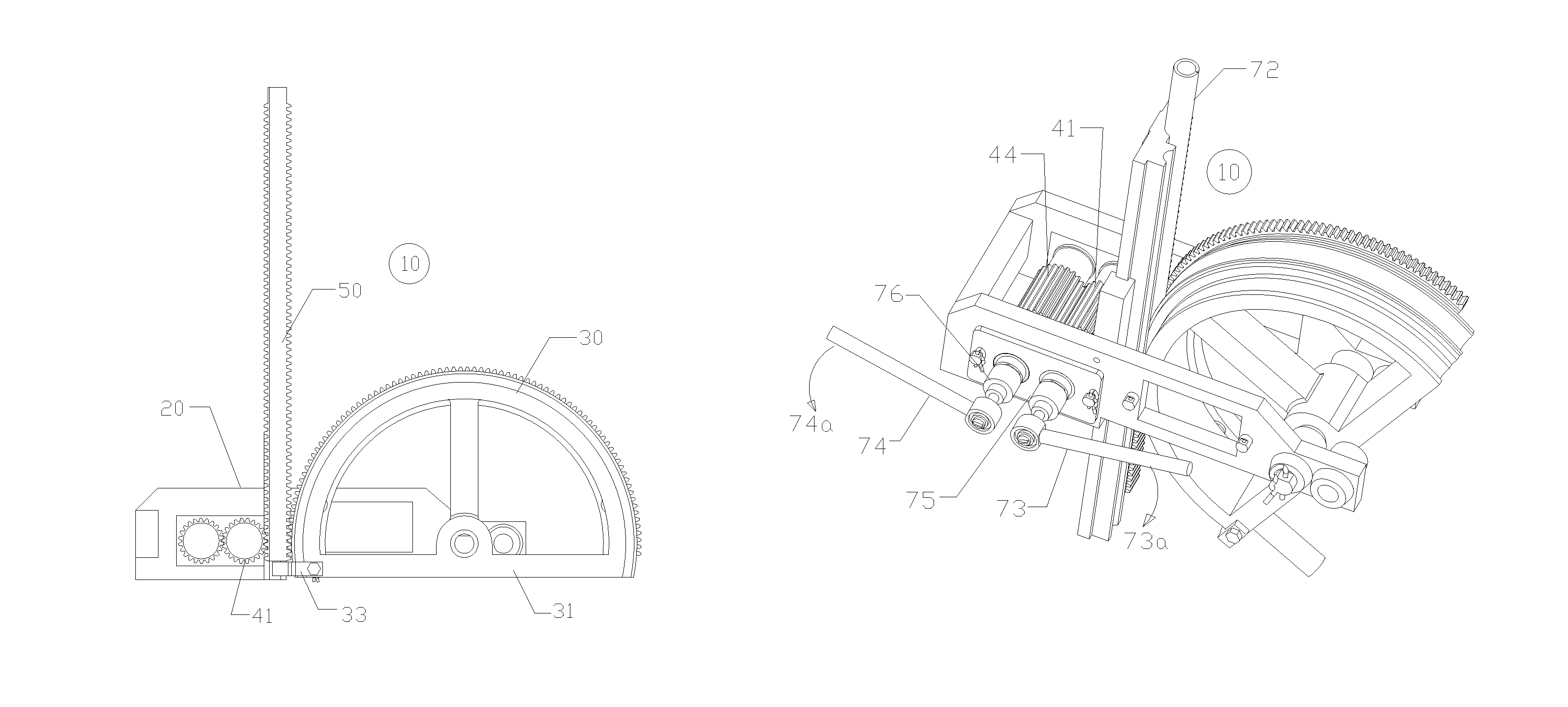
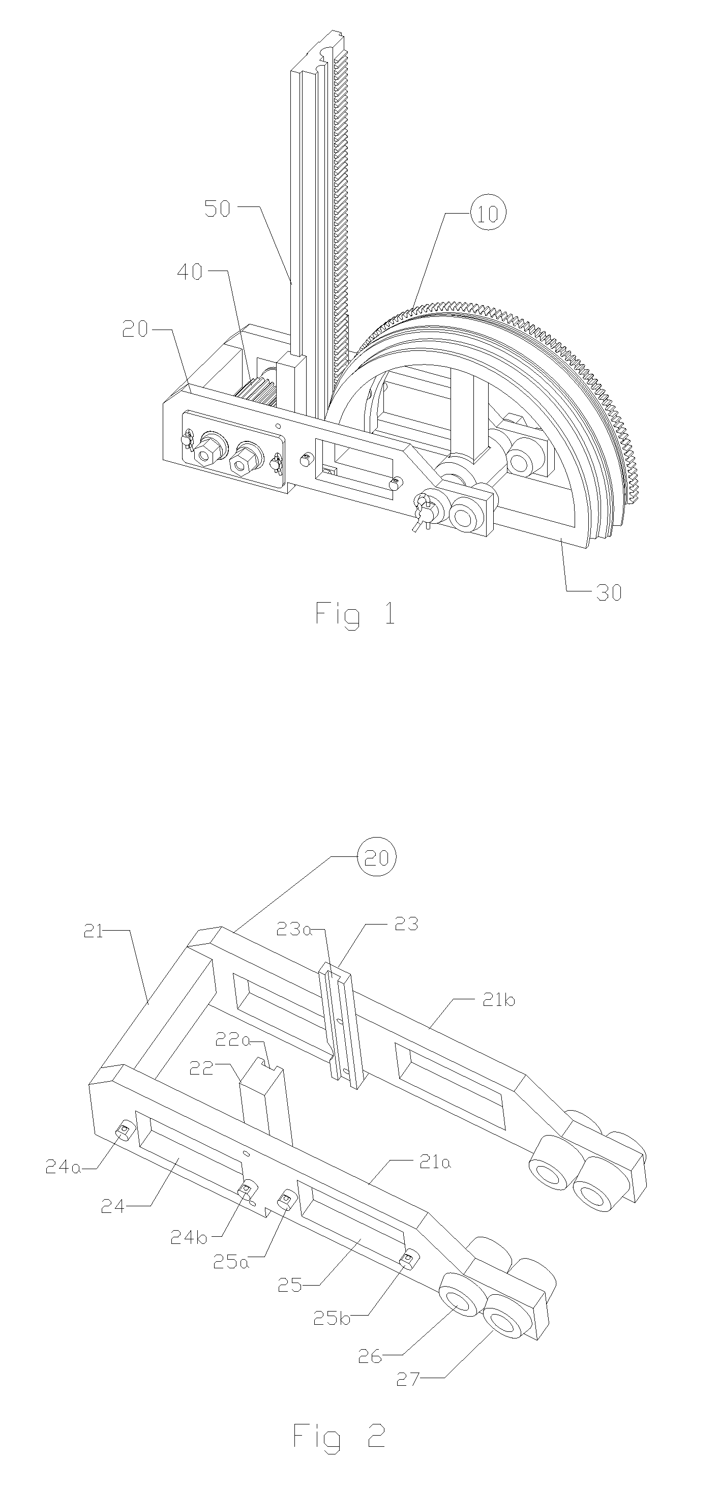
[0039]As shown in FIG. 1, according to the present invention, the pipe-bending apparatus 10 includes a frame assembly 20, a bending shoe assembly 30, a drive-gear assembly 40, and a gear rack 50.

[0040]FIG. 2 shows frame assembly 20, which includes a U-shaped frame 21 and firmly affixed U-channels 22 and 23 with U-shaped grooves 22a and 23a. Frame 21 includes a front arm 21a and a rear arm 21b, both having openings 24 and 25, through holes 26 and 27, and protrusions 24a, 24b, 25a and 25b (protrusions on frame rear portion 21 are not visible in this view).

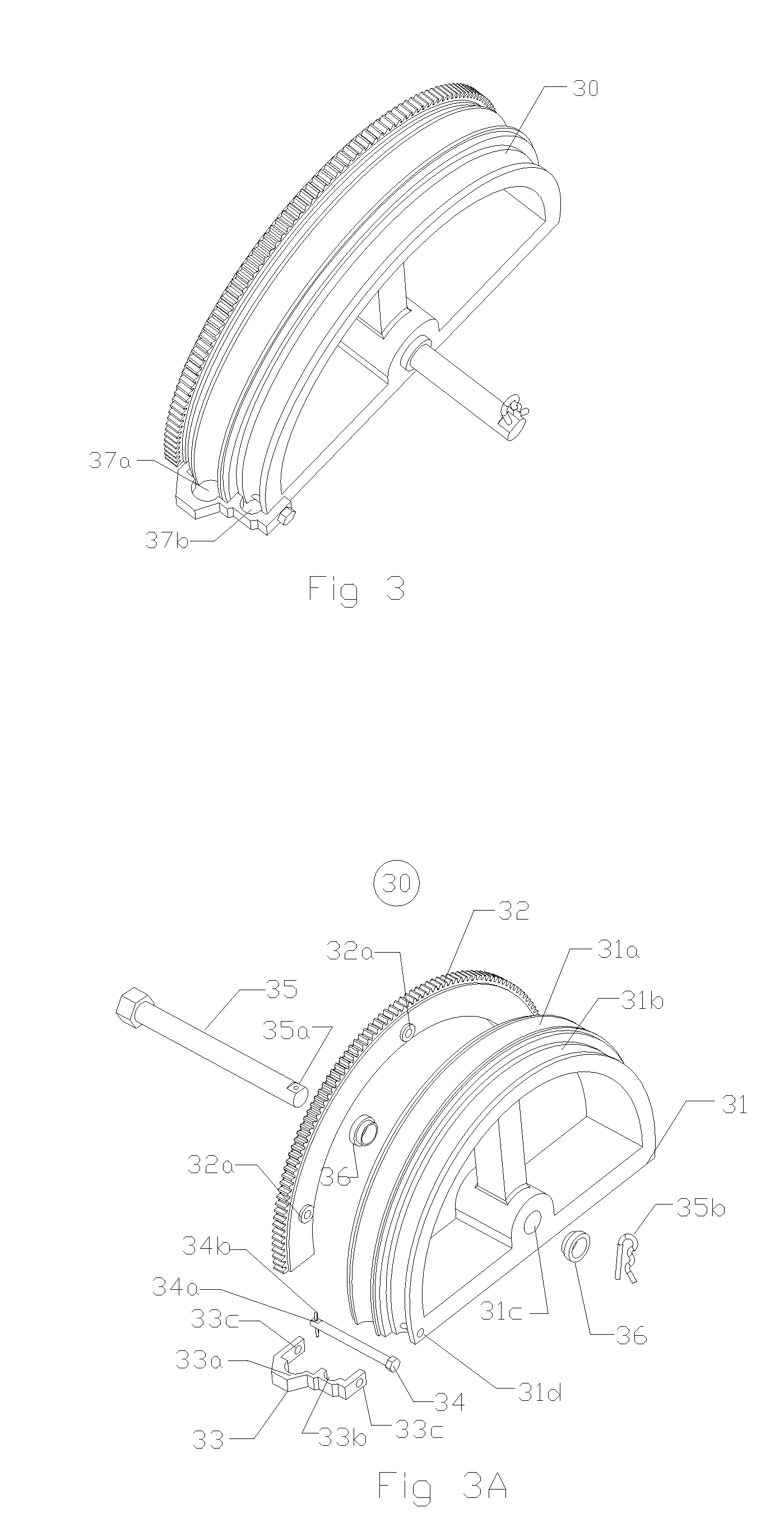
[0041]FIG. 3 shows bending shoe assembly 30 having two circumferential cavities 37a and 37b.

[0042]As shown in FIG. 3A, the components in bending shoe assembly 30 include: a bending shoe 31 with semicircular grooves 31a and 31b on the outer circumferential peripheral, holes 31c and 31d, a circumferential gear sector 32 with holes 32a, a U bracket 33 with semicircular grooves 33a and 33b, and holes 33c, a pin 34 with a hole 34a, a spr...

second embodiment

[0058]FIG. 11 shows a pipe-bending apparatus 110 according to the present invention.

[0059]As shown in FIG. 11, pipe-bending apparatus 110 includes a frame assembly 20, a bending shoe assembly 130, two of drive-gear assemblies 140, and a gear rack 50. Frame assembly 20 and gear rack 50 are the same as were described in the first embodiment of the present invention, so that these components will not be illustrated again.

[0060]FIG. 12 shows bending shoe assembly 130 having two circumferential cavities 137a and 137b.

[0061]FIG. 12A shows the components in bending shoe assembly 130 including: a bending shoe 131 having semicircular grooves 131a and 131b on the outer circumferential peripheral, two rows of circumferential internal gear teeth 137 and 138, holes 131c and 131d, a circumferential gear sector 132 having holes 132a, a U bracket 133 having semicircular grooves 133a and 133b, and holes 133c, a pin 134 having a hole 134a, a spring pin 134b, a pin 135 having a hole 135a, a spring pi...

third embodiment

[0074]FIG. 19 shows a pipe-bending apparatus 210 according to the present invention.

[0075]Pipe bending apparatus 210 including the installation of drive-gear assembly 40 (shown in FIG. 4 of the first embodiment of the present invention) into the pipe-bending apparatus 110 that was shown in FIG. 11. Ratchet 174 is used to drive drive-gear assembly 40 which in turn drives gear rack 50; and ratchet 173 is used to drive bending shoe 130, such that forces are applied more uniformly to the tool, thus causing less stresses and strains to the tool.


PUM

PropertyMeasurementUnit
lengthaaaaaaaaaa
outer circumferenceaaaaaaaaaa
forceaaaaaaaaaa

Abstract

The present invention of pipe-bending apparatus includes: a frame, a bending shoe having gear teeth and concave groove on its outer circumference, a drive-gear, a gear rack having gear teeth and concave groove on one surface and gear teeth only on opposite surface. The frame pivotally supports bending shoe and drive-gear, positions gear rack engaging bending shoe and drive-gear. When using the pipe-bending apparatus, a straight pipe is laid inside the groove on gear rack with one pipe portion secured to bending shoe. Force is applied to turn drive gear, with all gear components engaged, gear rack and pipe transverse downwards and turns bending shoe. With one pipe portion secured to and turning with bending shoe, the pipe begins bending inside the concave groove on bending shoe.

Description

CROSS-REFERENCES TO RELATED APPLICATIONS[0001]Not applicable.STATEMENT REGARDING FEDERALLY SPONSORED RESEARCH OR DEVELOPMENT[0002]Not applicable.TECHNICAL FIELD[0003]The present invention relates generally to a pipe bending system, and more particularly to an improved pipe bending apparatus.SUMMARY OF THE INVENTION[0004]The present invention pipe bending apparatus includes: a U-shaped frame having a front arm and a rear arm; a semicircular bending shoe having a row of gear teeth and a semicircular concave groove on outer circumference of the bending shoe; a cylindrical drive-gear having a row of gear teeth on its outer circular surface; and a rectangular gear rack board with gear teeth and a semicircular concave groove on one side of the board and gear teeth only on the opposite side. With two arms, the frame pivotally supports the bending shoe and the drive-gear, positions the gear rack in-between the bending shoe and the drive gear. When the pipe-bending apparatus is in use, a str...

Claims


Application Information

Patent Timeline
Patent Type & Authority Patents(United States)
IPC IPC(8): B21D7/04B21J9/18
CPCB21D7/021B21D7/024
Inventor HSUEH, PAULLAO, KIE HONG
Owner HSUEH PAUL
Why Eureka
Try Eureka