Structure of power transmission apparatus

a technology of power transmission apparatus and structure, which is applied in the direction of engine starters, machines/engines, and gears, etc., can solve the problems of slipping of the endless transmitting member on each pulley, difficulty in keeping the output, and difficulty in increasing the tension of the endless transmitting member to a required degree, so as to minimize the slippage increase the tension, and increase the tension of the endless transmitting member

Active Publication Date: 2016-05-03
DENSO CORP
View PDF12 Cites 7 Cited by
  • Summary
  • Abstract
  • Description
  • Claims
  • Application Information

AI Technical Summary

Benefits of technology

[0011]It is therefore an object to provide an improved structure of a power transmission system designed to minimize slippage of an endless transmitting member on a pulley without having to finely control an operation of an auxiliary device when it is required to start an internal combustion engine.
[0012]According to one aspect of the invention, there is provided a power transmission system which works to transmit power, as produced by an internal combustion engine, to a first auxiliary device and a second auxiliary device. The first auxiliary device is operable either in a motor mode or in a regenerative mode. The power transmission system comprises: (a) a driving pulley which is joined to a drive shaft of the internal combustion engine to be rotatable along with rotation of the drive shaft; (b) a first auxiliary device pulley which is joined to a shaft of the first auxiliary device to be rotatable along with rotation of the shaft of the first auxiliary device; (c) a second auxiliary device pulley which is joined to a shaft of the second auxiliary device to be rotatable along with rotation of the shaft of the second auxiliary device; (d) an endless transmitting member which is wound around the driving pulley, the first auxiliary device pulley, and the second auxiliary device pulley; (e) a tensioner pulley which is rotatable in contact with the endless transmitting member, the tensioner pulley being also movable relative to the internal combustion engine; (f) an auto-tensioner which is equipped with a tensioner body, the tensioner body working to extend or contract in a given direction to move the tensioner pulley relative to the internal combustion engine, thereby changing a degree of tension of the endless transmitting member; (g) a biasing mechanism which biases the tensioner body to extend in the given direction; and (h) a stroke inhibitor which works to inhibit the tensioner body from contracting. The auto-tensioner may work to eliminate slippage of the endless transmitting member between the driving pulley and the first auxiliary device pulley or between the driving pulley and the second auxiliary device pulley when the first auxiliary device operates in the regenerative mode.
[0014]Specifically, the controller controls the operation of the first auxiliary device so as to extend the tensioner body in the given direction for increasing the tension of the endless transmitting member in the reverse rotation control mode. This keeps the tension of the endless transmitting member increased when it is required to start the first auxiliary device to operate in the motor mode in the engine start mode, thereby minimizing the slippage of the endless transmitting member on each of the first and second auxiliary device pulleys when the internal combustion engine is cranked.
[0015]After the internal combustion engine starts, the controller enters the inhibition releasing mode to cause the tensioner body to contract, thereby decreasing the tension of the endless transmitting member which has been increased by reverse rotation of the first auxiliary device in the reverse rotation control mode. This avoids an undesirable increase in frictional resistance of the endless transmitting member on each of the first and second auxiliary device pulleys and minimizes the wear or damage to the endless transmitting member.
[0016]The controller, as already described, works to predict the reversing timing when the drive shaft (i.e., the internal combustion engine) will start being reversed and control the operation of the first auxiliary device based on the reversing timing in the reverse rotation control mode. Specifically, the controller stops the reverse rotation of the first auxiliary device immediately before or at the moment when the reversing timing is reached, thereby keeping the tensioner body at a desired extended position without causing the drive shaft to rotate in the reverse direction. This eliminates the need for finely controlling the operation of the first auxiliary device to output a degree of torque within a range which is higher than that permitting the tensioner body to extend in the given direction thereof and is lower than that causing the drive shaft to rotate in the reverse direction. The power transmission system is, therefore, capable of controlling the slippage of the endless transmitting member on each of the first and second auxiliary device pulleys without having to finely control the operation of the first auxiliary device when the internal combustion engine is started.

Problems solved by technology

When the above torque range is narrow, it results in a difficulty in keeping the output, as produced by the given accessory, within the torque range at all times.
When the torque, as produced by the given accessory which reverses in the reverse rotation control step, is lower than that causing the tensioner body to extend in the given direction, it will result in a difficulty in increasing the tension of the endless transmitting member to a required degree, which may lead to the slippage of the endless transmitting member on each of the pulleys.

Method used


Image

  • Structure of power transmission apparatus
  • Structure of power transmission apparatus
  • Structure of power transmission apparatus

Examples


first embodiment

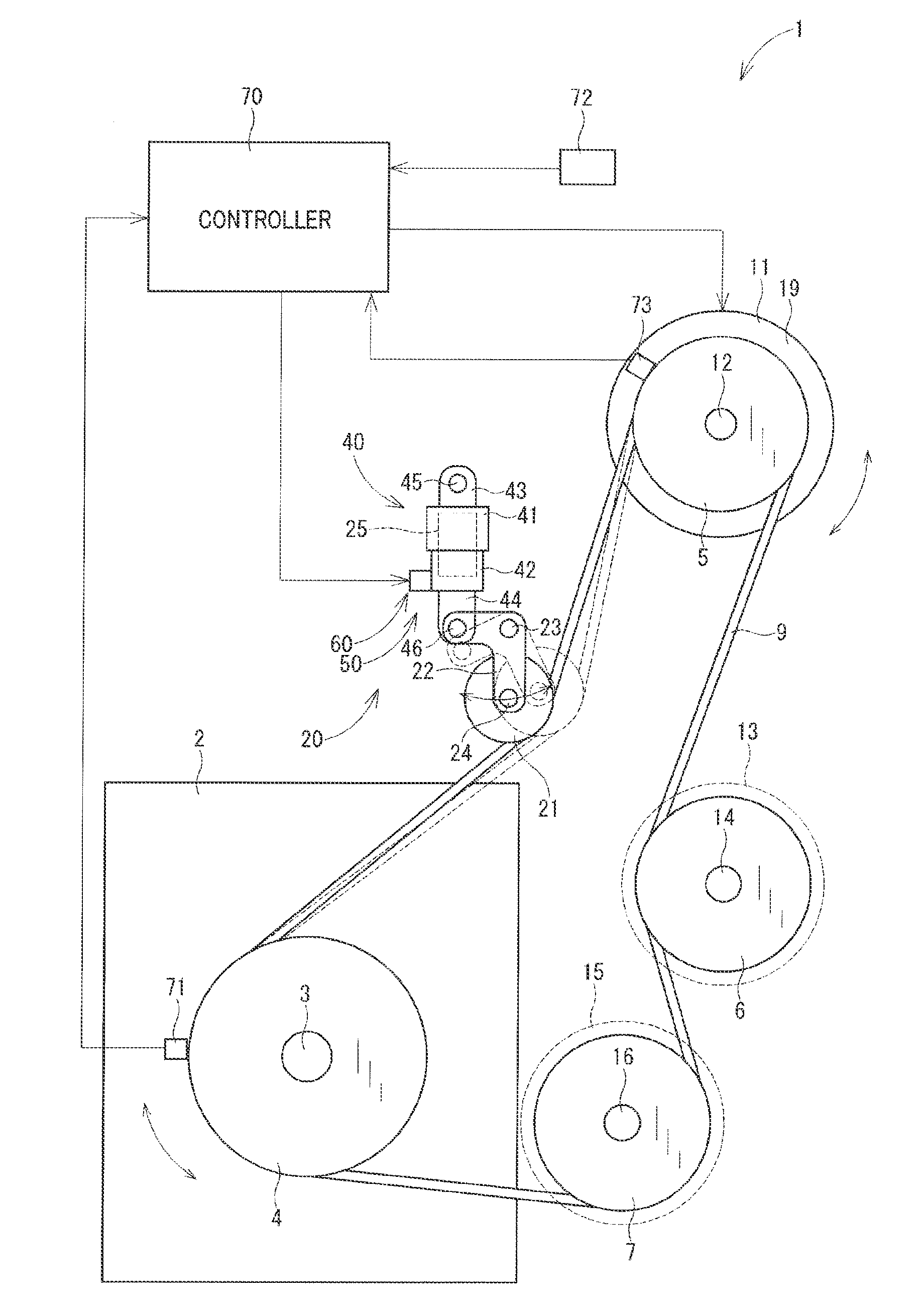
[0026]FIG. 1 illustrates a power transmission system 1 according to the first embodiment. The power transmission system 1, as referred to herein, is installed in an automotive vehicle, not shown, which is equipped with an internal combustion engine 2. The power transmission system 1 works to transmit output power (i.e., torque), as produced by the engine 2, to a given accessory 11 and other accessories 13 and 15 mounted in the vehicle. The accessories 11, 13, and 15, as referred to herein, are auxiliary electric or mechanical devices which are supplied with or transmit power or torque from or to the internal combustion engine 2. The given accessory 11 will also be referred to below as a first auxiliary device. The accessories 13 and 15 will also be referred to below as second auxiliary devices.

[0027]The power transmission system 1 is, as clearly illustrated in FIG. 1, disposed near the engine 2. The power transmission system 1 includes a driving pulley 4, a given accessory pulley 5,...

second embodiment

[0111]FIG. 5 illustrates the power transmission system 1 according to the second embodiment which is different in physical structure thereof and operation of the reverse rotation step made by the ECU 70 from the first embodiment.

[0112]The power transmission system 1 is also equipped with a position sensor 74 installed on the tensioner body 40. The position sensor 74 measures the distance between the upper body 41 and the lower body 42, that is, an extended / contracted position of the tensioner body 40. The position sensor 74 outputs a signal indicative of the position of the tensioner body 40 to the ECU 70. The ECU 70 analyzes the output from the position sensor 74 and determines the extended / contracted position of the tensioner body 40.

[0113]The prediction of the reversing timing, as made by the ECU 70, will be described below with reference to FIG. 6.

[0114]FIG. 6 is a flowchart of a sequence of logical steps or reversing timing determination program executed by the ECU 70 when or a...

third embodiment

[0133]The power transmission system 1 according to the third embodiment will be described below which is different in how the ECU 70 determines the reversing timing from the first embodiment. Other arrangements are identical, and explanation thereof in detail will be omitted here.

[0134]When it is required to predict the reversing timing when the drive shaft 3 is expected to reverse, the ECU 70 analyzes the output from the angular position sensor 73 to determine the angular position of the given accessory pulley 5 and calculates the reversing timing as a function of the angular position of the given accessory pulley 5 and a target angular position θISG of the given accessory pulley 5 to be achieved in the reverse rotation control step. The target angular position θISG is given by

θISG=(Lb−La) / 2πRISG  (5)

[0135]Specifically, when the reversing timing is reached, that is, the angular position of the given accessory pulley 5, as measured by the position sensor 73, reaches the target angul...


PUM


Abstract

A power transmission system transmits power from a drive shaft of an internal combustion engine to a first and a second auxiliary device through a belt. An auto-tensioner extends or contracts to change the tension of the belt. A controller rotates the first auxiliary device in a reverse direction to loosen the belt to cause the auto-tensioner to extend to increase the tension of the belt and calculates a reversing timing when the drive shaft will be reversed as a result of increasing of the tension of the belt. The controller inhibits the tensioner body from contracting immediately before or when the reversing time is reached to keep the tension of the belt at an increased degree, thereby eliminating the slippage of the belt on each pulley without having to finely control the operation of the first auxiliary device when the internal combustion engine is started.

Description

CROSS REFERENCE TO RELATED DOCUMENT[0001]The present application claims the benefit of priority of Japanese Patent Application No. 2013-259996 filed on Dec. 17, 2013, the disclosure of which is incorporated herein by reference.BACKGROUND OF THE INVENTION[0002]1. Technical Field[0003]This disclosure relates generally to a power transmission apparatus designed to transmit power, as produced by an internal combustion engine, to auxiliary devices.[0004]2. Background Art[0005]There are known power transmission systems which work to transmit output power of an internal combustion engine to a given accessory and other accessories mounted in, for example, an automobile using an endless transmitting member such as a belt. The given accessory is used as, for instance, an engine starter to start the internal combustion engine. The given accessory may be rotated by the output power of the internal combustion engine along with the other accessories in a regenerative mode of operation to generate...

Claims


Application Information

Patent Timeline
Patent Type & Authority Patents(United States)
IPC IPC(8): F16H7/22B60W20/00F02N15/02F16H7/12F16H7/08F02N11/04F02N15/08
CPCF16H7/1281B60W20/00F02N15/02Y10T477/23F16H2007/0861F16H2007/0885Y10S903/909F02N11/04F02N15/08
Inventor NOGUCHI, HITOSHIOKADA, HIROSHIODA, SHUZONAKANO, TOMOAKIYAMASHITA, YOSHIHIROYAMAMOTO, YOUSUKEHARA, KAZUHISA
Owner DENSO CORP
Why Eureka
Try Eureka