Fluid-filled vibration damping device

a technology of vibration damping device and fluid filling, which is applied in the direction of shock absorbers, machine supports, mechanical equipment, etc., can solve the problems of inability to exhibit satisfactory damping effect and difficulty in achieving the required vibration damping performance of conventional fluid filling vibration damping device, and achieve excellent space utilization, and effective vibration damping performance

Active Publication Date: 2005-06-16
SUMITOMO RIKO CO LTD
View PDF3 Cites 28 Cited by
  • Summary
  • Abstract
  • Description
  • Claims
  • Application Information

AI Technical Summary

Benefits of technology

[0009] It is therefore one object of this invention to provide a fluid-filled vibration damping device of novel construction, which is capable of exhibiting excellent vibration damping effect for vibration of a plurality of frequency ranges or over a wide frequency range, and is suitably utilized, for example, as an automotive engine mount.

Problems solved by technology

Therefore, the conventional fluid-filled vibration damping device still ensures its advantageous damping effect only at a narrow frequency range, and is not able to exhibit satisfactory damping effect.
For instance, while an engine mount for automotive vehicle is required to exhibit excellent vibration damping performance not only for vibration excited during running conditions, e.g., low frequency and large amplitude vibration, such as engine shakes, and high frequency small amplitude vibration such as booming noises, but for vibration excited during idling conditions, e.g., medium frequency and medium amplitude vibration corresponding to engine idling vibration, it is still difficult for the conventional fluid-filled vibration damping device to sufficiently achieve the required vibration damping performance.

Method used


Image

  • Fluid-filled vibration damping device
  • Fluid-filled vibration damping device
  • Fluid-filled vibration damping device

Examples


first embodiment

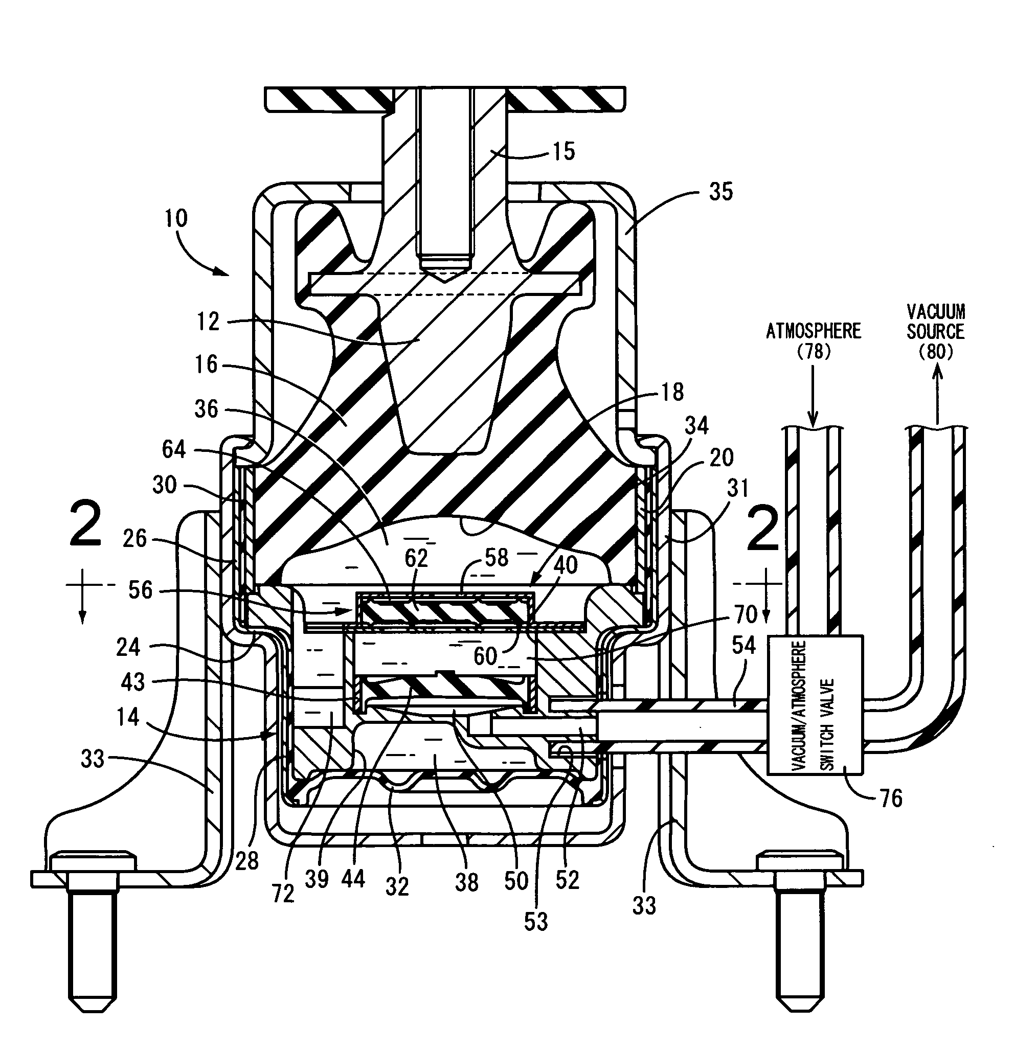
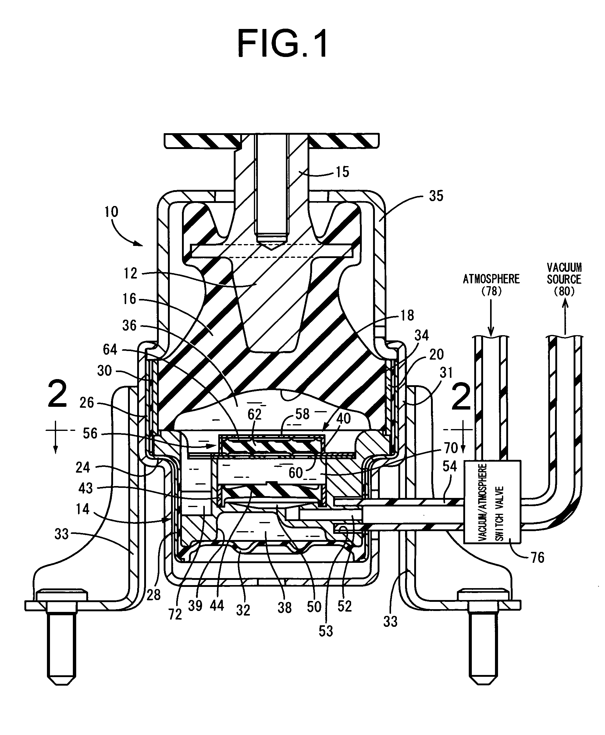
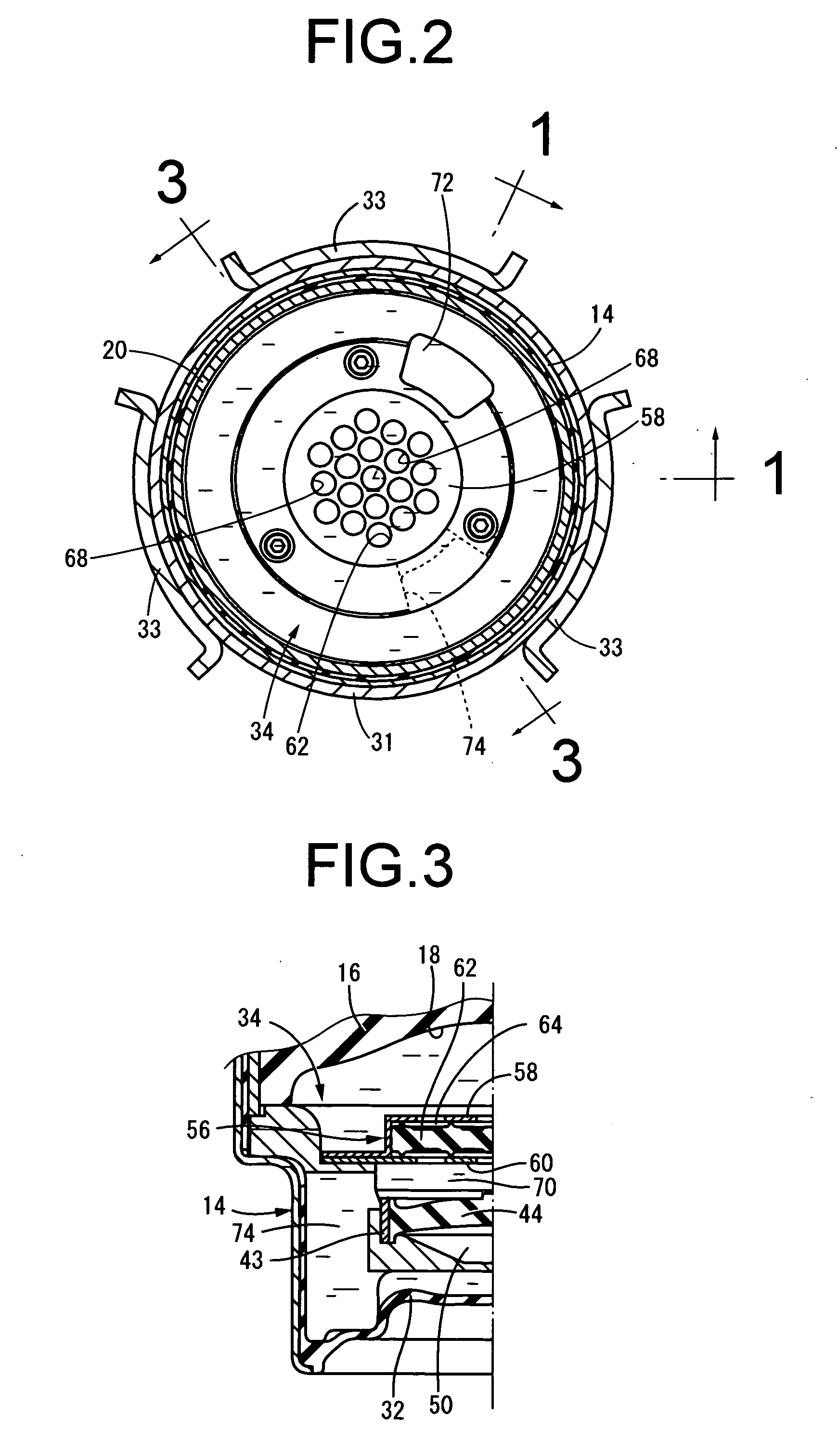
[0055] Referring first to FIGS. 1-3, shown is an engine mount 10 for an automotive vehicle, having construction according to a fluid-filled vibration damping device of the present invention. The engine mount 10 includes a first mounting member 12 of metal, a second mounting member 14 of metal, and an rubber elastic body 16 by which are elastically connected the first mounting member 12 and the second mounting member 14 disposed spaced away from each other. While it is not depicted in the drawings, the engine mount 10 is installed on the vehicle such that the first mounting member 12 is fixed to the power unit side of the vehicle, while the second mounting member 14 is fixed to the body side of the vehicle, whereby the engine mount 10 fixedly supports the power unit on the body of the vehicle in a vibration damping fashion, like conventional engine mounts. In the following description, the vertical direction of the engine mount 10 shall be conformed to the vertical direction as seen ...

second embodiment

[0100] In the engine mount 90 of the present invention, elastic deformation of the rubber elastic plate 44, which partially define the wall of the medial chamber 70, is permitted by means of equilibrium chamber 38 situated behind (lower side in FIG. 11) thereof. Therefore, the engine mount 90 is able to exhibit the substantially same damping effect as in the engine mount 88 of the second embodiment shown in FIG. 10.

[0101] That is, the engine mount 90 will provide a functional construction for low frequency and large amplitude vibration, which is identical with that shown in FIG. 5. For medium frequency and medium amplitude vibration, the engine mount 90 will provide a functional construction as shown in FIG. 13, which is substantially equivalent to those shown in FIGS. 7 and 10. For high frequency and small amplitude vibration, the engine mount 90 will provide a functional construction identical with that shown in FIG. 9.

[0102] Referring next to FIG. 14, shown is an engine mount 98...


PUM


Abstract

A fluid-filled vibration damping device including: an elastic body connecting a first and a second mounting member, defining a pressure receiving chamber undergoing pressure fluctuation during input of vibration; an equilibrium chamber defined by a flexible layer for permitting its volume change; a first orifice passage connecting the pressure receiving chamber and equilibrium chamber; a medial chamber disposed between the pressure receiving chamber and equilibrium chamber; a second orifice connecting the pressure receiving and medial chambers, being tuned to a frequency higher than does the first orifice passage; a pressure fluctuation transmitting mechanism disposed between the pressure receiving and medial chambers for a restricted pressure transmission between chambers by restrictive displacement of its movable member; and a pressure regulating rubber plate defining the medial chamber, regulating pressure fluctuation in the medial chamber by its elastic deformation.

Description

INCORPORATED BY REFERENCE [0001] The disclosure of Japanese Patent Application No. 2003-415765 filed on Dec. 12, 2003 including the specification, drawings and abstract is incorporated herein by reference in its entirety. BACKGROUND OF THE INVENTION [0002] 1. Field of the Invention [0003] The present invention relates generally to vibration damping devices suitably used as an automobile engine mount, and the like, for example, and more particularly to an engine mount of novel construction, which is capable of advantageously exhibiting vibration damping effect with respect to various kinds of vibration, on the basis of flow action of the fluid sealed therein. [0004] 2. Description of the Related Art [0005] A fluid-filled vibration damping device is known as one type of vibration dam ping device installed between two members constituting a vibration transmitting system, like an engine mount interposed between a body and a power unit of a automotive vehicle. Typically, a fluid-filled v...

Claims


Application Information

Patent Timeline
Patent Type & Authority Applications(United States)
IPC IPC(8): F16F13/06F16F5/00F16F13/10F16F13/18F16F13/26F16F15/02
CPCF16F13/264
Inventor MAENO, HAJIMEMURAMATSU, ATSUSHI
Owner SUMITOMO RIKO CO LTD
Why Eureka
Try Eureka