Temperature compensation circuit

a temperature compensation circuit and circuit technology, applied in the direction of oscillator tubes, oscillator generators, electrical equipment, etc., can solve the problems of reducing the functional control pull range of oscillators, imposing more stringent requirements on their functional behavior, and difficult to construct temperature compensation signal generators

Active Publication Date: 2005-06-16
SEIKO EPSON CORP
View PDF11 Cites 52 Cited by
  • Summary
  • Abstract
  • Description
  • Claims
  • Application Information

AI Technical Summary

Benefits of technology

[0036] The first module produces a compensation sub-signal that is directly proportional to temperature and has a temperature offset by appropriate balancing of another CTAT signal source and a Proportional To Absolute Temperature (PTAT) signal source. The temperature offset is achieved by assuring that the CTAT signal source is of greater magnitude than the PTAT signal source for temperatures below a predetermined transition temperature, and assuring that the CTAT signal source is of lesser magnitude than the PTAT signal source for temperatures higher than the predetermined transition temperature. Depending on the characteristics of the CTAT and PTAT signal sources used, the transition temperature may be made proximate to, or equal to, the assigned temperature offset. The difference of the outp

Problems solved by technology

This temperature compensation requirement reduces the functional control pull range of the oscillator which imposes more stringent requirements on its functional behavior.
In practice, however, it is difficult to construct a temperature compensation signal generator that produces an output compensation signal that varies with temperature in manner sufficiently inverse to that of variable oscillator 1002 over a wide temperature range.
However, an oscillator's natural frequency drift due to temperature might not be uniform with temperature.
Thus direct use of a temperature sensor uniformly dependent on temperature to compensate an oscillator's temperature drift may not be suitable for all oscillators over extended temperature ranges

Method used


Image

  • Temperature compensation circuit
  • Temperature compensation circuit
  • Temperature compensation circuit

Examples


Embodiment Construction

[0056] Preferred embodiments of the present invention are described below with reference to the accompanying figures.

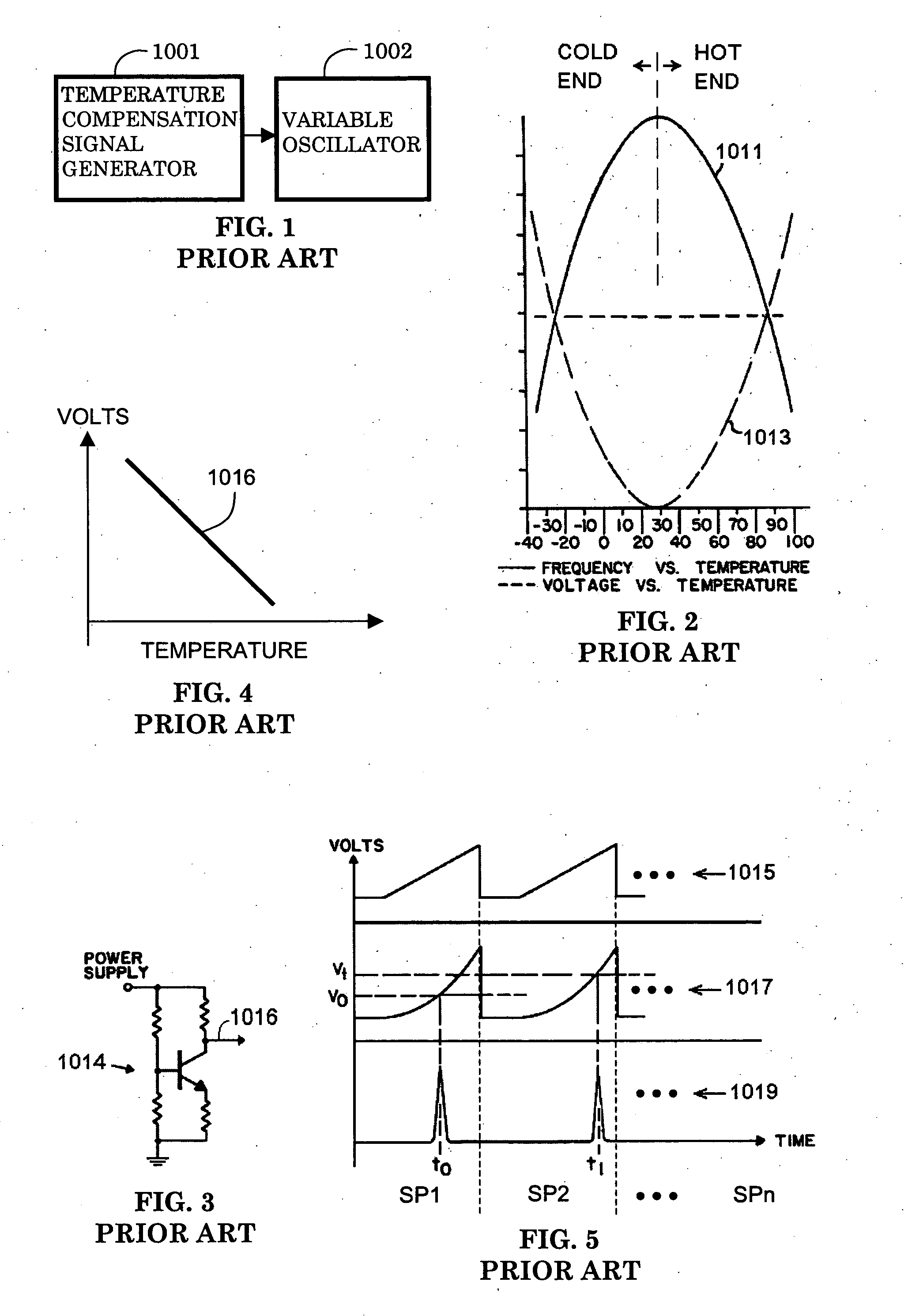
[0057] Different oscillator types respond differently to changes in temperature. An understanding of how an oscillator's output frequency shifts under a varying temperature my be obtained by observing the oscillator's frequency-to-temperature characteristic curve, i.e. a plot of how the oscillator's output frequency naturally varies over a predefined temperature range. For illustrative purposes, the present invention is exemplarily applied to a surface acoustic wave (SAW) resonator based oscillator (i.e. an oscillator using a SAW type filter), but it is to be understood that the present invention may equally be applied to other types of oscillators with minor modification to presented procedure and circuitry.

[0058] With reference to FIG. 11, the qualitative shape of a frequency-to-temperature characteristic curve of a SAW resonator based oscillator without temperatu...


PUM


Abstract

A temperature compensation circuit has multiple configurable modules to produce a compensation signal whose temperature characteristic curve is the inverse of the frequency-to-temperature characteristic curve of a specified oscillator. A set of first modules that produce first sub-signals directly proportional to temperature and a set of second modules that produce second sub-signals inversely proportional to temperature have their outputs summed at a summation node. Each module may adjust the strength and shaped of its temperature characteristic sub-signal, and each module may optionally be assigned a temperature offset that impedes the output of its corresponding sub-signal until the assigned temperature offset is reached. Each of the first and second modules includes a signal generator and an optional temperature offset circuit, which may be incorporated into the operation of the signal generator. To produce a compensation signal to compensate a SAW resonator, a first module having a temperature offset and being directly proportional to temperature is summed with a second module having no temperature offset and being inversely proportional to temperature.

Description

BACKGROUND OF THE INVENTION [0001] 1. Field of the Invention [0002] The present invention relates generally to a temperature compensation circuits, and more particularly to circuits that compensate the temperature versus frequency characteristic of variable frequency oscillators, such as Surface Acoustic Wave resonators. [0003] 2. Description of the Related Art [0004] An oscillator's output frequency will drift from a target, or center, frequency with variations in temperature. In precision frequency devices, frequency drift due to temperature variation is of primary concern since an oscillator's ambient temperature will fluctuate under normal use. Therefore, it is customary to provide an oscillator circuit with temperature compensation circuitry to attempt to stabilize the oscillator's output frequency over a predetermined operating temperature range. [0005] Voltage (VCO) or current (CCO) controlled variable frequency oscillators are frequently used in precision clock generators fo...

Claims


Application Information

Patent Timeline
IPC IPC(8): H03L1/02
CPCY10S331/03H03L1/022
Inventor MELTZER, DAVID
Owner SEIKO EPSON CORP
Why Eureka
Try Eureka