Impedance transformation ratio control in film acoustically-coupled transformers

a technology of acoustically coupled transformers and transformers, which is applied in the direction of impedence networks, electrical apparatus, solid-state devices, etc., can solve the problems of coil-based transformers becoming impractical, not all transformers have all of these properties, and the autotransformer not providing electrical isolation

Active Publication Date: 2005-06-16
AVAGO TECH INT SALES PTE LTD
View PDF13 Cites 93 Cited by
  • Summary
  • Abstract
  • Description
  • Claims
  • Application Information

AI Technical Summary

Problems solved by technology

However, not all transformers have all of these properties.
For example, an autotransformer does not provide electrical isolation.
At UHF and microwave frequencies, coil-based transformers become impractical due to such factors as losses in the core, losses in the windings, capacitance between the windings, and a difficulty to make them small enough to prevent wavelength-related problems.
Transformers also exist that are based on micro-machined coupled coils sets and are small enough that wavelength effects are unimportant.
However such transformers have issues with high insertion loss and low primary to secondary isolation and low primary to secondary isolation.
All the transformers just described for use at UHF and microwave frequencies have dimensions that make them less desirable for use in modern miniature, high-density applications such as cellular telephones.
Such transformers also tend to be high in cost because they are not capable of being manufactured by a batch process and because they are essentially an off-chip solution.
Moreover, although such transformers typically have a bandwidth that is acceptable for use in cellular telephones, they typically have an insertion loss greater than 1 dB, which is too high.
Opto-couplers are not used at UHF and microwave frequencies due to the junction capacitance of the input LED, non-linearities inherent in the photodetector, limited power handling capability and insufficient isolation to give good common mode rejection.

Method used


Image

  • Impedance transformation ratio control in film acoustically-coupled transformers
  • Impedance transformation ratio control in film acoustically-coupled transformers
  • Impedance transformation ratio control in film acoustically-coupled transformers

Examples


embodiment 202

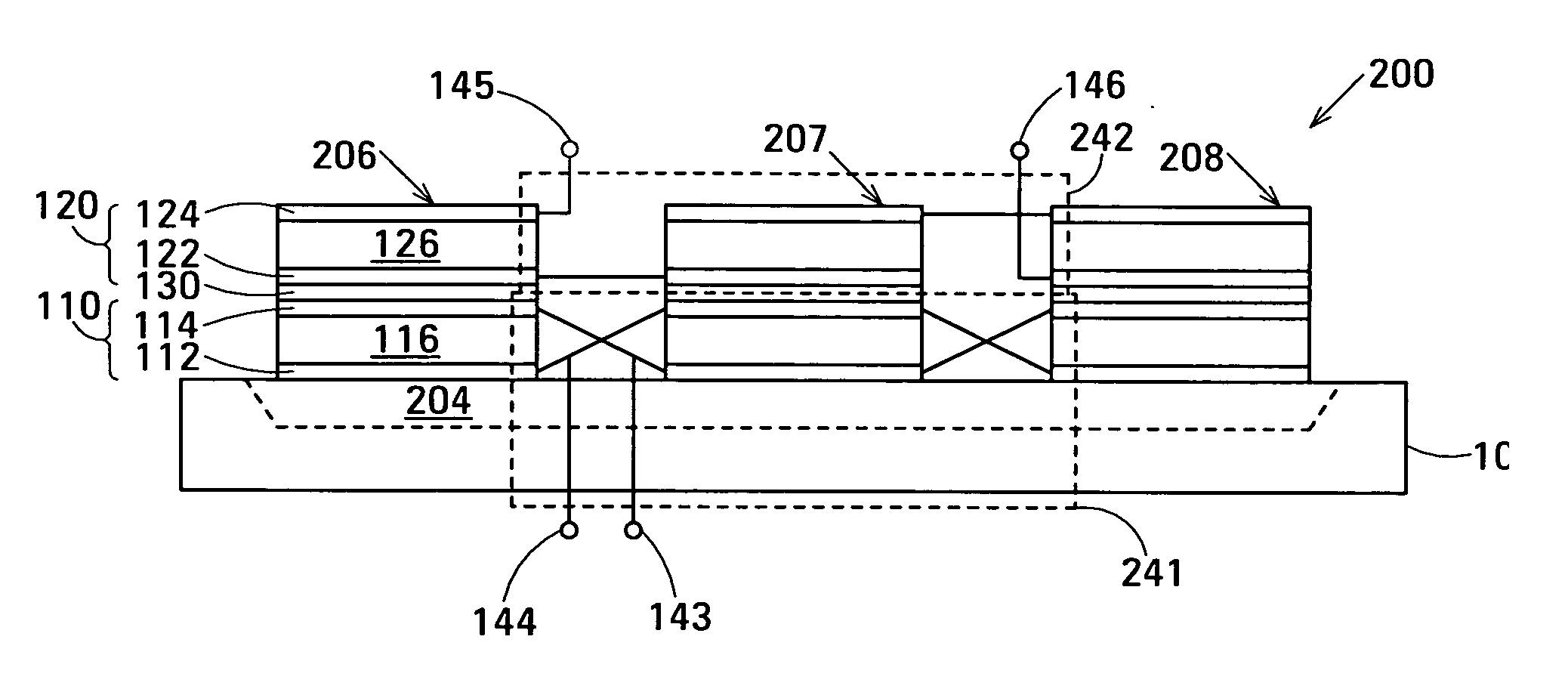
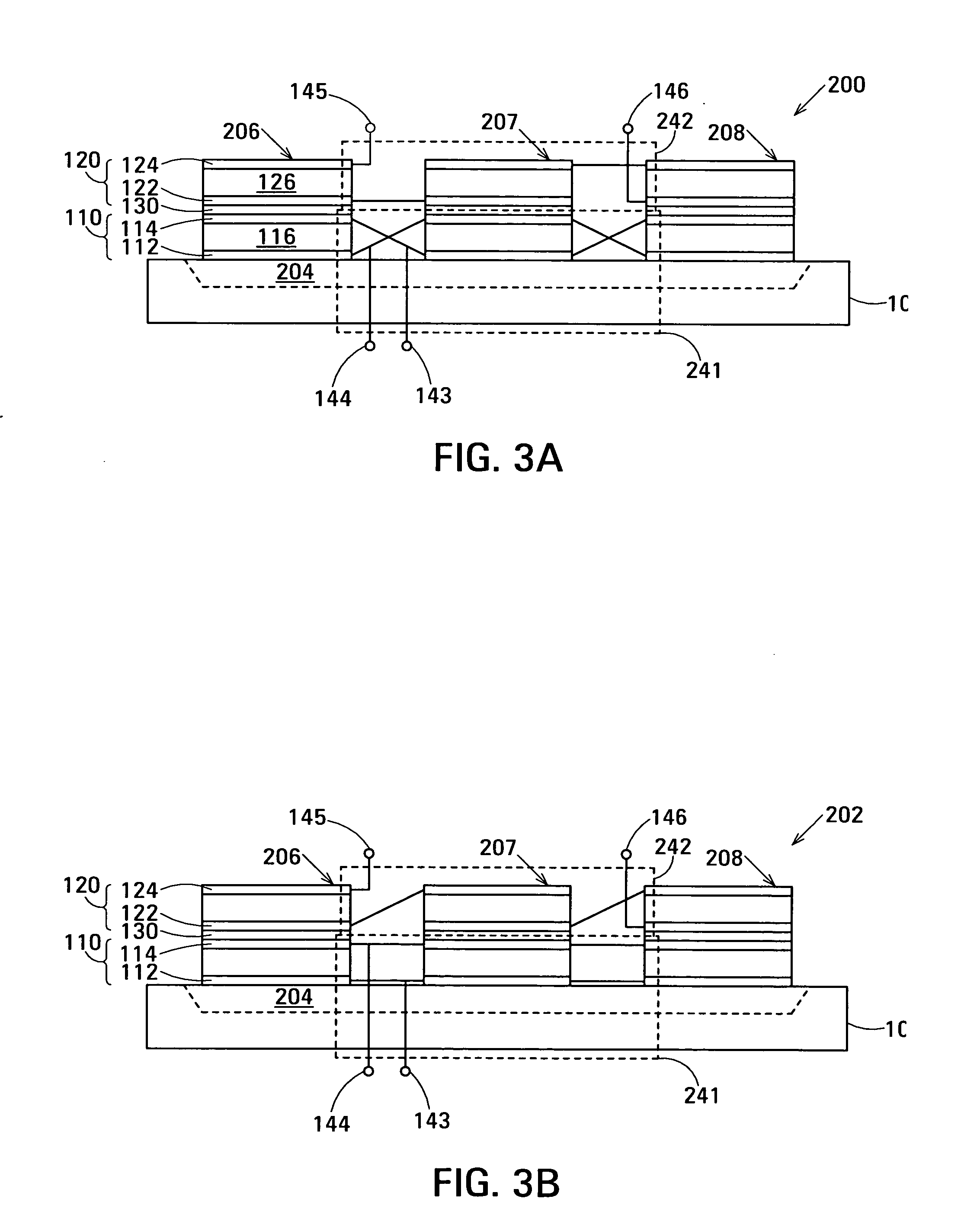
[0062]FIG. 3B shows an alternative embodiment 202 of a three-DSBAR film acoustically-coupled transformer (FACT) in accordance with the invention also having an impedance transformation ration of 1:9. In this embodiment, electrical circuit 241 connects the lower FBARs 110 of DSBARs 206, 207 and 208 in parallel and to terminals 143 and 144. Additionally, electrical circuit 242 connects the upper FBARs 120 of DSBARs 206, 207 and 208 in anti-series between terminals 145 and 146.

[0063] Embodiments of electrical circuit 241 may interconnect the lower FBARs 110 of DSBARs 206, 207 and 208 in circuit arrangements different from those shown in FIGS. 3A and 3B to provide different impedances between terminals 143 and 144. Additionally, embodiments of electrical circuit 242 may interconnect the upper FBARs 120 of DSBARs 206, 207 and 208 in circuit arrangements different from those shown in FIGS. 3A and 3B to provide different impedances between terminals 145 and 146. The different impedances ca...

first embodiment

[0065]FIG. 3C shows electrical circuit 241 or electrical circuit 242 that connects FBARs 311, 313 and 315 in parallel between terminals T1 and T2. In this embodiment, the impedance between terminals T1 and T2 is Z / 3, where Z is the impedance of each of the FBARs 311, 313 and 315. FBARs 311, 313 and 315 are assumed to be equal in impedance. FIG. 3C illustrates the circuit arrangement in which electrical circuit 241 interconnects the lower FBARs 110 of DSBARs 206-208 in FIG. 3B.

second embodiment

[0066]FIG. 3D shows electrical circuit 241 or electrical circuit 242 that connects FBARs 311 and 313 in series and additionally connects FBAR 315 in parallel with the series combination of FBARs 311 and 313 between terminals T1 and T2. In this embodiment, the impedance between terminals T1 and T2 is (2Z2 / 3Z)=2Z / 3.


PUM

PropertyMeasurementUnit
insertion lossaaaaaaaaaa
thickaaaaaaaaaa
thicknessaaaaaaaaaa

Abstract

The film acoustically-coupled transformer (FACT) has decoupled stacked bulk acoustic resonators (DSBARs), a first electrical circuit and a second electrical circuit. Each of the DSBARs has a lower film bulk acoustic resonator (FBAR), an upper FBAR and an acoustic decoupler. The upper FBAR is stacked on the lower FBAR and the acoustic decoupler is located between the FBARs. Each FBAR has opposed planar electrodes and a piezoelectric element between the electrodes. The first electrical circuit interconnects the lower FBARs. The second electrical circuit interconnects the upper FBARs. The FBARs of one of the DSBARs differ in electrical impedance from the FBARs of another of the DSBARs. The FACT has an impedance transformation ratio greater than 1:m2, where m is the number of DSBARs. The actual impedance transformation ratio depends on the ratio of the impedances of the FBARs.

Description

RELATED APPLICATION [0001] This disclosure is a Continuation-in-Part of U.S. patent application Ser. No. 10 / 699,481 of John D. Larson III and Richard Ruby. This application is also related to U.S. patent application Ser. No. ______ of John D. Larson III and Richard Ruby entitled Film Acoustically-Coupled Transformer With Increased Common Mode Rejection (Agilent Docket No. 10031284-1), U.S. patent application Ser. No. ______ of John D. Larson III and Stephen Ellis entitled Pass Bandwidth Control in Decoupled Stacked Bulk Acoustic Resonator Devices (Agilent Docket No. 10040955-1), and U.S. patent application Ser. No. ______ of John D. Larson III, Richard Ruby and Stephen Ellis entitled Film Acoustically-Coupled Transformer (Agilent Docket No. 10041306-1), all filed on the filing date of this application. The above applications are all assigned to the assignee of this application and the disclosures of the above applications are incorporated into this application by reference.BACKGROUN...

Claims


Application Information

Patent Timeline
Patent Type & Authority Applications(United States)
IPC IPC(8): H03H9/13H03H9/60H03H9/17
CPCH03H9/132H03H9/584Y10T29/42H03H9/605H03H9/587H01L2224/48091H01L2224/49175H01L2924/00014H03H9/60H03H9/0095
Inventor LARSON, JOHN D. IIISARKESHIK, NAGHMEHELLIS, STEPHEN L.
Owner AVAGO TECH INT SALES PTE LTD
Why Eureka
Try Eureka