Image sensing apparatus and method of controlling same

a technology of image sensing and image, applied in the field of image sensing apparatus, can solve the problems of large number of such unit pixels, high cost, and mechanical precision, and achieve the effects of high cost, easy control, and high precision

Inactive Publication Date: 2005-06-16
CANON KK
View PDF7 Cites 26 Cited by
  • Summary
  • Abstract
  • Description
  • Claims
  • Application Information

AI Technical Summary

Benefits of technology

[0017] The present invention has been made in view of the circumstances described above and its object is to achieve high-speed electronic shutter control in which image degradation ascribable to the time needed for read-out scan is reduced without the addition of new circuitry.

Problems solved by technology

This requires mechanical precision and involves difficult control at the same time.
Although optical-plane shutters of improved control precision are used in some image sensing apparatus, these are high in cost because they require a complicated mechanism and high precision.
In actuality, however, a very large number of such unit pixels are arrayed in two dimensions.
A problem with the operation of the rolling electronic shutter of the prior art described above is that the accumulation timings at the top and bottom of the screen differ by the length of time necessary for scanning of the screen.
Accordingly, read-out and scanning of image signals cannot be performed at high speed and a large disparity develops between the accumulation timings at the top and bottom of the screen, especially in a case where the screen is composed of a large number of pixels.
This invites a rise in cost, which accompanies an increase in the surface area of the semiconductor chip.
Further, if use is made of a MOS-type image sensing device, photoelectric charge will be produced in the floating depletion area in a case where the image sensing device has such a structure that light leaks into the floating depletion area.
This means that the light must be blocked by a mechanical shutter after the transfer of charge to the floating depletion area.
As a consequence, exposure unevenness develops in the scanning direction of the mechanical shutter and this results in a

Method used


Image

  • Image sensing apparatus and method of controlling same
  • Image sensing apparatus and method of controlling same
  • Image sensing apparatus and method of controlling same

Examples


Embodiment Construction

[0031] A preferred embodiment of the present invention will be described in detail in accordance with the accompanying drawings.

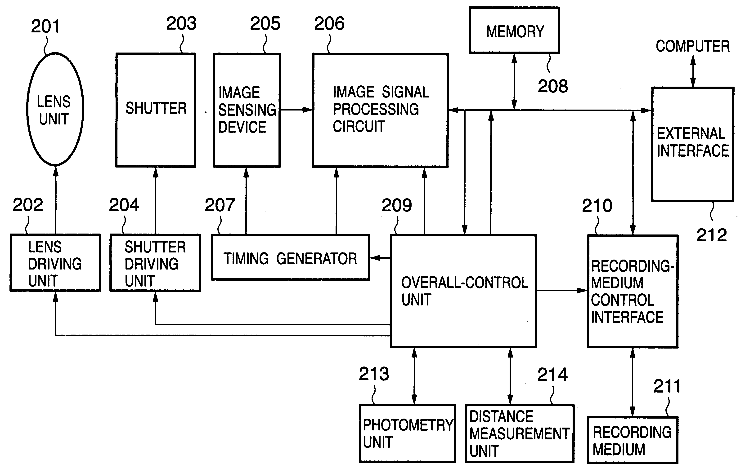
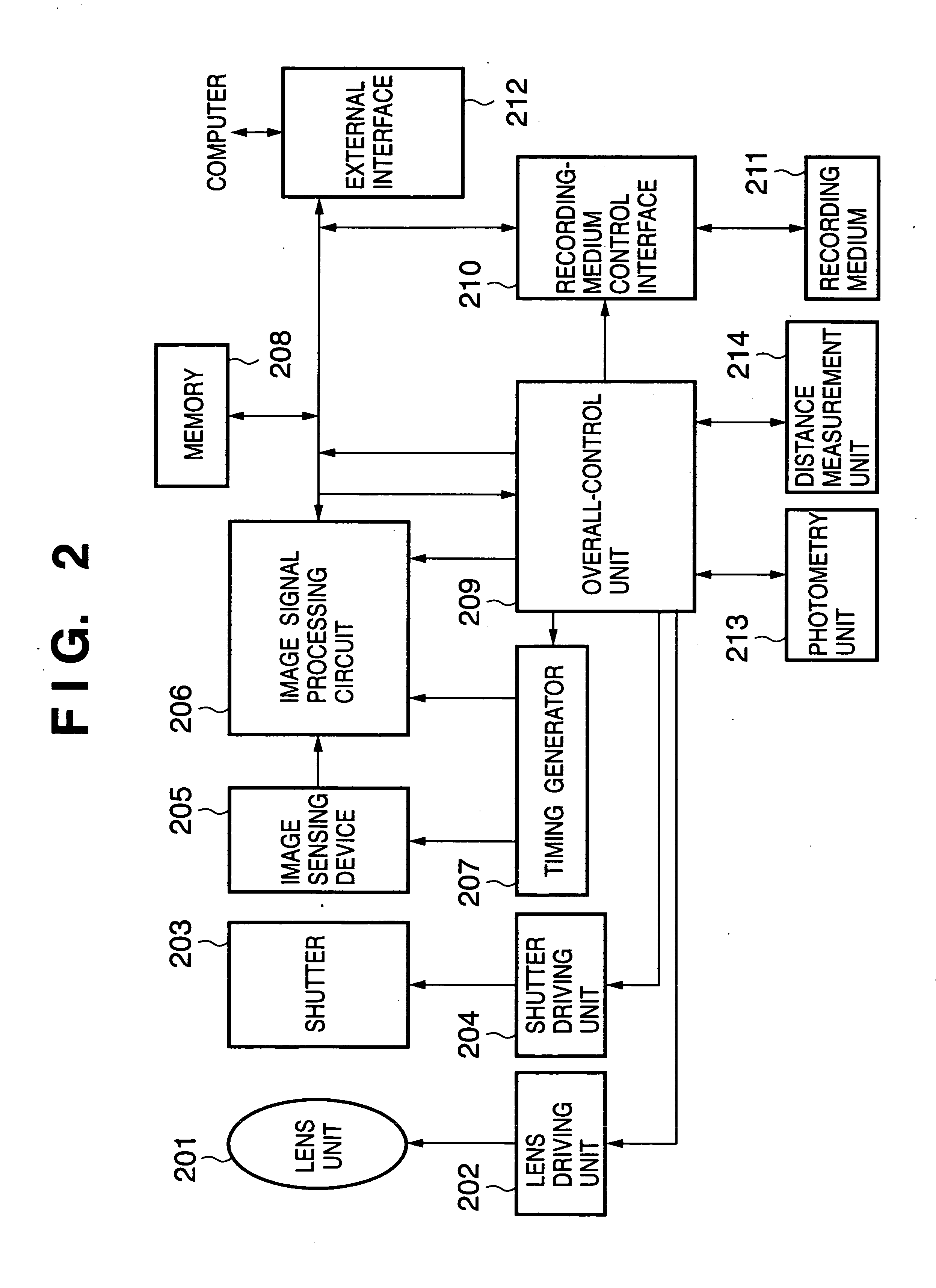
[0032] Since an image sensing device having a structure similar to that of the prior art shown in FIG. 6 is used in this embodiment, the device need not be described again here. In this embodiment, however, the method of controlling drive of the image sensing device (the operation of the vertical scanning circuit 112 in FIG. 6) differs from that of the prior art and therefore the method of controlling drive will be described in detail.

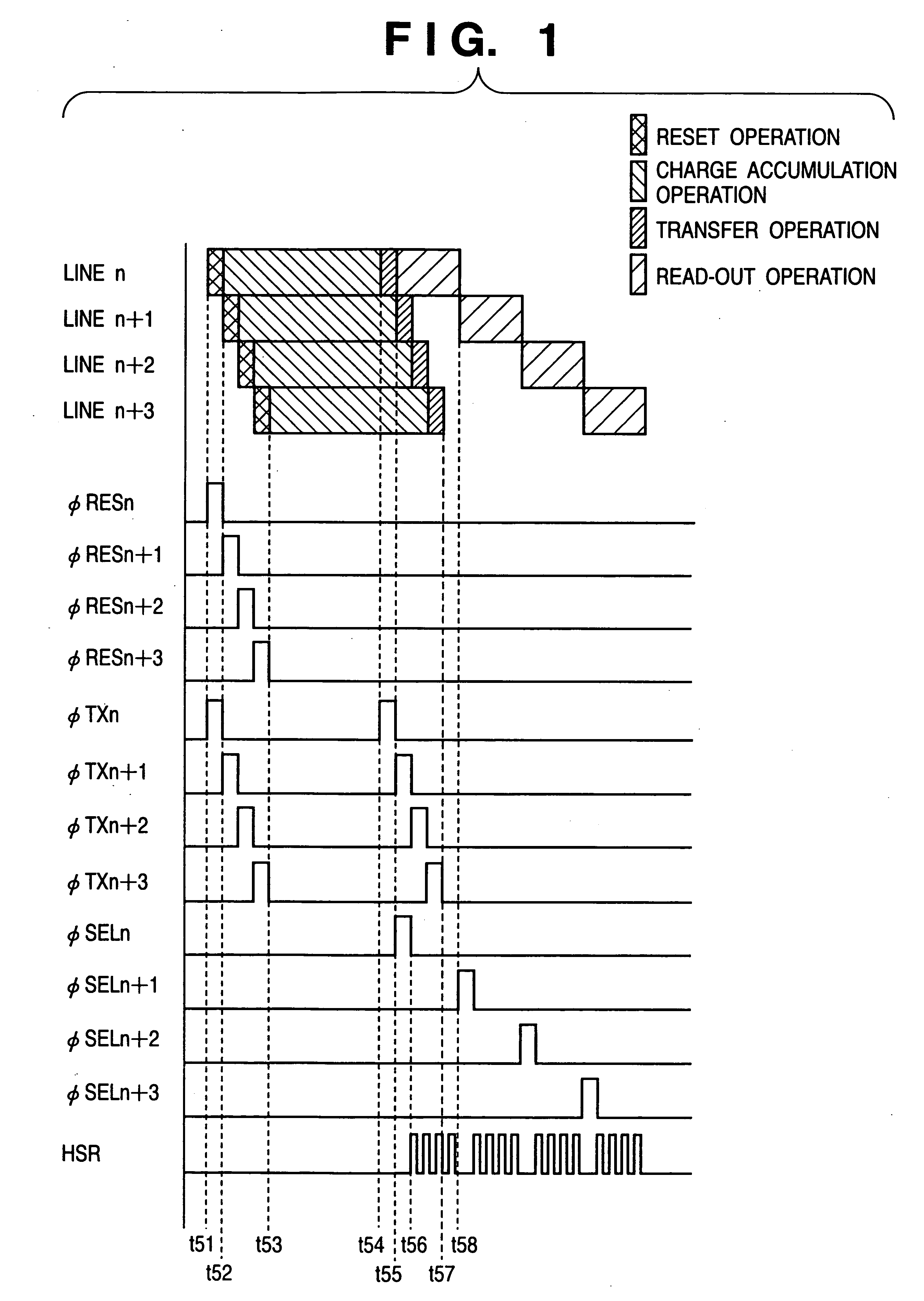
[0033]FIG. 1 is a timing chart useful in describing the driving method and operating sequence of the image sensing device shown in FIG. 6 in an embodiment of the present invention. In order to simplify the description regarding FIG. 1, the description rendered line n+3 scanned and selected by the vertical scanning circuit 112. First, from time t51 to time t52 in regard to line n, a reset operation is performed by applying th...


PUM


Abstract

Disclosed is an image sensing apparatus comprising a plurality of two-dimensionally arrayed pixels each having a photodiode and a floating depletion area for temporarily storing a charge signal that has accumulated in the photodiode; an output unit that outputs the charge signal, which has been transferred to the floating depletion area, successively pixel by pixel; a scanning unit having a reset mode for resetting the photodiodes and floating depletion areas successively by prescribed unit, a first transfer mode for transferring the charge signal, which has accumulated in the photodiodes, to the floating depletion areas successively by the prescribed unit at prescribed time intervals upon lapse of a prescribed period of time from start of reset, and a second transfer mode for transferring the charge signal, which has been transferred to the floating depletion areas, to the output unit. Before operation of the second transfer mode is performed with respect to a plurality of the prescribed units, the scanning unit transfers the charge signal, which has accumulated in the photodiodes, to the floating depletion areas successively by the prescribed unit at the prescribed time intervals with respect to the

Description

FIELD OF THE INVENTION [0001] This invention relates to an image sensing apparatus that employs a solid-state image sensing device, and to a method of driving this apparatus. More particularly, the invention relates to the structure of an image sensing apparatus for implementing a high-speed shutter operation in accurate fashion, and to a method of driving this apparatus. BACKGROUND OF THE INVENTION [0002] In an image sensing apparatus that employs a solid-state image sensing device such as a CCD or CMOS, the exposure time of the image sensing device is controlled using a mechanical shutter, which is a mechanical light-shield member. To realize a short exposure time, it is necessary to drive the shutter at high speed. This requires mechanical precision and involves difficult control at the same time. Although optical-plane shutters of improved control precision are used in some image sensing apparatus, these are high in cost because they require a complicated mechanism and high prec...

Claims


Application Information

Patent Timeline
Patent Type & Authority Applications(United States)
IPC IPC(8): H04N5/335H04N5/353H04N5/357H04N5/369H04N5/376
CPCH04N5/3532H04N25/531
Inventor KISHI, TAKAFUMITAKEDA, NOBUHIRO
Owner CANON KK
Why Eureka
Try Eureka