Rotary folder-type mobile communication terminal

a mobile communication terminal and folder type technology, applied in the direction of telephone set construction, substation equipment, interconnection arrangements, etc., can solve the problems of insufficient arrangement space for conventional rotary folder type mobile communication terminals, inability to provide the arrangement space necessary for arranging digital sensors and other parts, etc., to achieve the effect of increasing the thickness of the folder part and sufficient arrangement spa

Inactive Publication Date: 2005-06-16
PANTECH CO LTD
View PDF10 Cites 38 Cited by
  • Summary
  • Abstract
  • Description
  • Claims
  • Application Information

AI Technical Summary

Benefits of technology

[0010] It is an object of the present invention to provide a rotary folder-type mobile communication terminal that is capable of providing a large arrangement space sufficient to arrange large-sized parts for a camera without increasing the thickness of a folder part of the rotary folder-type mobile communication terminal as compared to the conventional rotary folder-type mobile communication terminal.

Problems solved by technology

As a result, the conventional rotary folder-type mobile communication terminal does not provide a large arrangement space sufficient to arrange a large-sized camera having a great number of pixels, for example, several mega-pixels.
Especially in the case of the camera having a great number of pixels, a digital sensor is still used since no camera sensor for mobile communication terminals has yet been developed.
Consequently, when the digital sensor is applied to the conventional rotary folder-type mobile communication terminal, it is very difficult to provide an arrangement space necessary for arranging the digital sensor and other parts of the camera inside the left-side or right-side space of the upper end of the folder part where the rotating hinge part is fixed.
As a result, the thickness of the folder part is inevitably increased.

Method used


Image

  • Rotary folder-type mobile communication terminal
  • Rotary folder-type mobile communication terminal
  • Rotary folder-type mobile communication terminal

Examples


Embodiment Construction

[0034] Now, a preferred embodiment of the present invention will be described in detail with reference to the accompanying drawings.

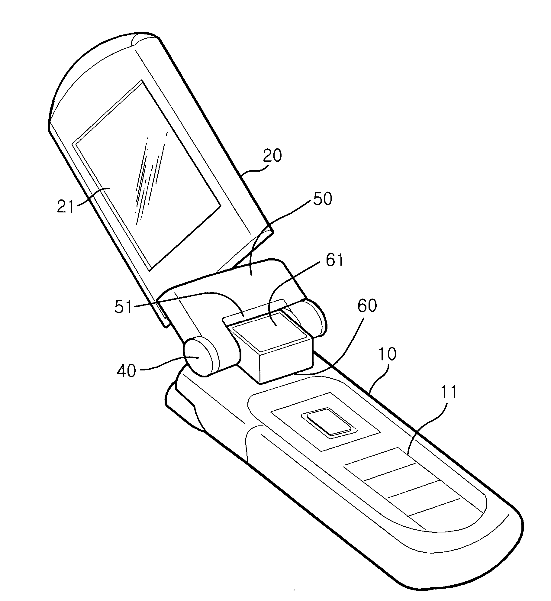
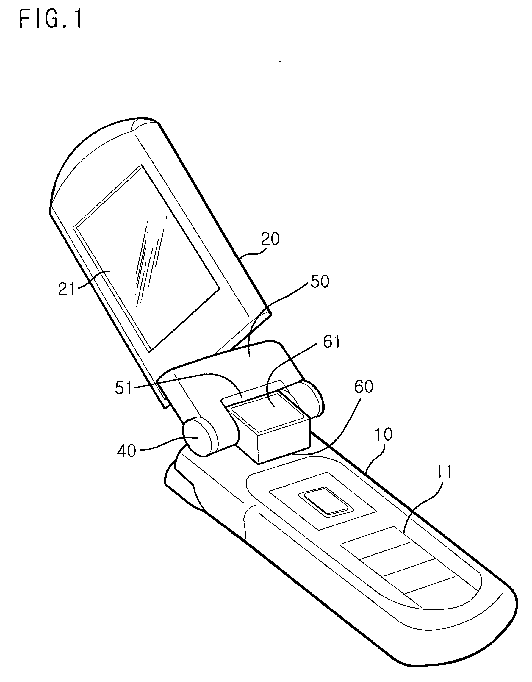
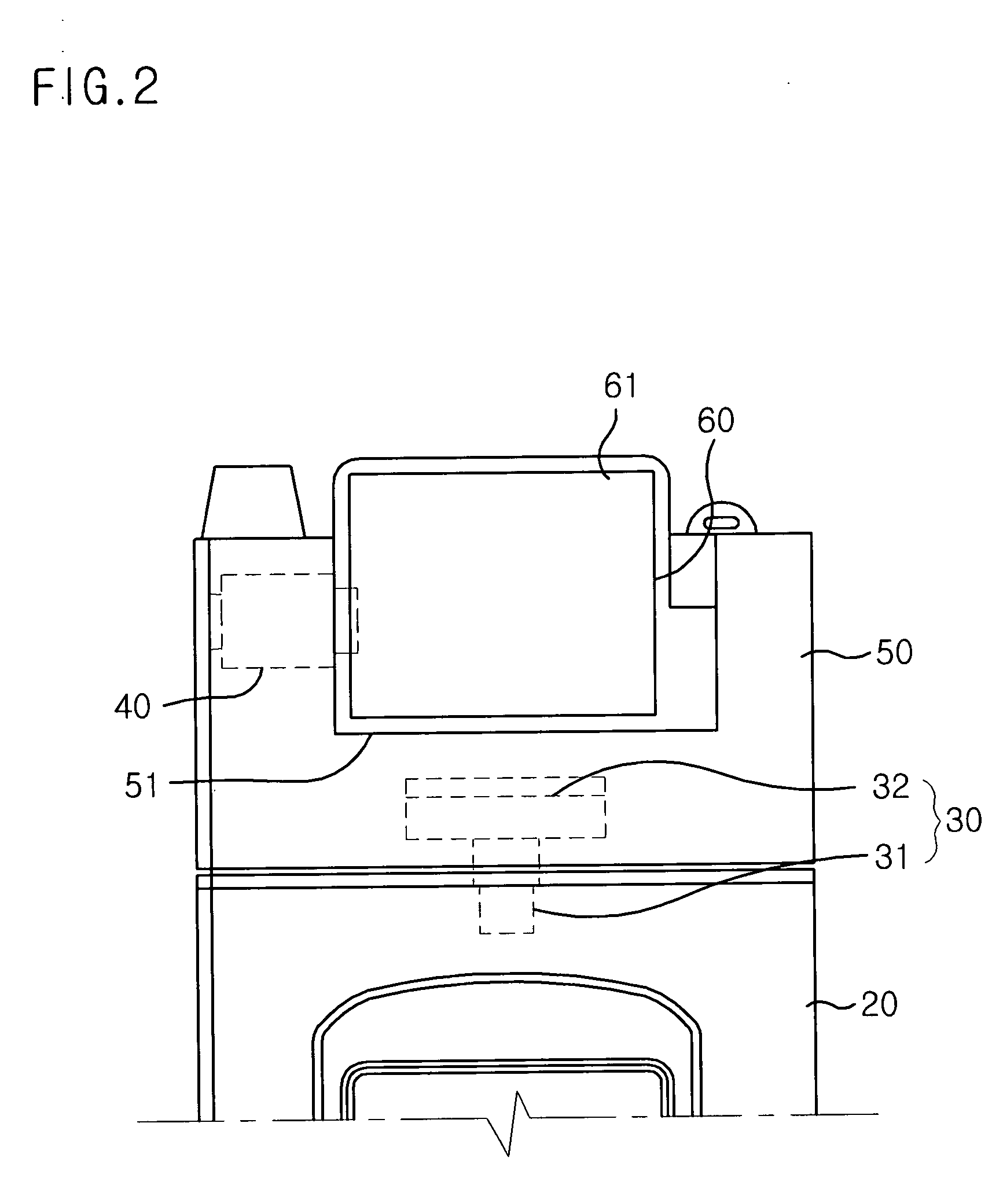
[0035]FIG. 1 is a perspective view showing a rotary folder-type mobile communication terminal according to a preferred embodiment of the present invention with a folder part of the rotary folder-type mobile communication terminal unfolded open, and FIG. 2 is a front view, in part, showing the rotary folder-type mobile communication terminal according to the preferred embodiment of the present invention with the folder part of the rotary folder-type mobile communication terminal folded closed.

[0036] The construction of the rotary folder-type mobile communication terminal according to the preferred embodiment of the present invention will now be described in detail with reference to FIGS. 1 and 2.

[0037] The rotary folder-type mobile communication terminal of the present invention comprises: a body part 10 having a button-operating unit 11 disposed on t...


PUM


Abstract

Disclosed herein is a rotary folder-type mobile communication terminal that is capable of providing a large arrangement space sufficient to arrange a large-sized camera having a great number of pixels and related camera parts therein without increasing the thickness or the size of a folder part of the rotary folder-type mobile communication terminal. The rotary folder-type mobile communication terminal comprises a body part, a folder part, a folding hinge part mounted on a prescribed axis for opening/closing the folder part, and a rotating hinge part mounted on another prescribed axis different from the axis of the folding hinge part while being spaced apart from the folding hinge part for rotating the folder part. The body part has a button-operating unit disposed on the upper surface thereof, and the folder part has an LCD window facing the body part. With the provision of the rotary folder-type mobile communication terminal according to the present invention, a large-sized component, such as a large-sized camera having a great number of pixels, can be easily and stably arranged at an appropriate position in the mobile communication terminal.

Description

BACKGROUND OF THE INVENTION [0001] 1. Field of the Invention [0002] The present invention relates to a rotary folder-type mobile communication terminal, and more particularly to a rotary folder-type mobile communication terminal that is capable of providing a large arrangement space sufficient to arrange a camera having a great number of pixels and related camera parts therein. [0003] 2. Description of the Related Art [0004] A rotary folder-type mobile communication terminal with a foldable and simultaneously rotatable folder part is known. [0005]FIG. 7 is a partial perspective view, cut away in part, showing a conventional rotary folder-type mobile communication terminal. The construction and operation of the conventional rotary folder-type mobile communication terminal will be described below with reference to FIG. 7. [0006] As shown in FIG. 7, the conventional rotary folder-type mobile communication terminal comprises: a body part 100 having a button-operating unit disposed on th...

Claims


Application Information

Patent Timeline
Patent Type & Authority Applications(United States)
IPC IPC(8): H04B1/00H04B1/38H04M1/02
CPCH04B1/38H04M1/0264H04M1/0212H04B1/40
Inventor WOO, SEONG-TAEK
Owner PANTECH CO LTD
Why Eureka
Try Eureka