Network apparatus and program product

a network apparatus and program technology, applied in the field of network apparatus and program products, can solve problems such as manual input in setting positional information, and achieve the effect of simple work

Inactive Publication Date: 2005-06-16
SANYO ELECTRIC CO LTD
View PDF7 Cites 70 Cited by
  • Summary
  • Abstract
  • Description
  • Claims
  • Application Information

AI Technical Summary

Benefits of technology

[0008] It is an object of the present invention to provide a network apparatus and a program product with which a user can set positional information intuitively by simple work in connecting appliances to a network system.

Problems solved by technology

In this case, again, it is assumed that complicated work such as manual input in setting the positional information is required.

Method used


Image

  • Network apparatus and program product
  • Network apparatus and program product
  • Network apparatus and program product

Examples


first embodiment

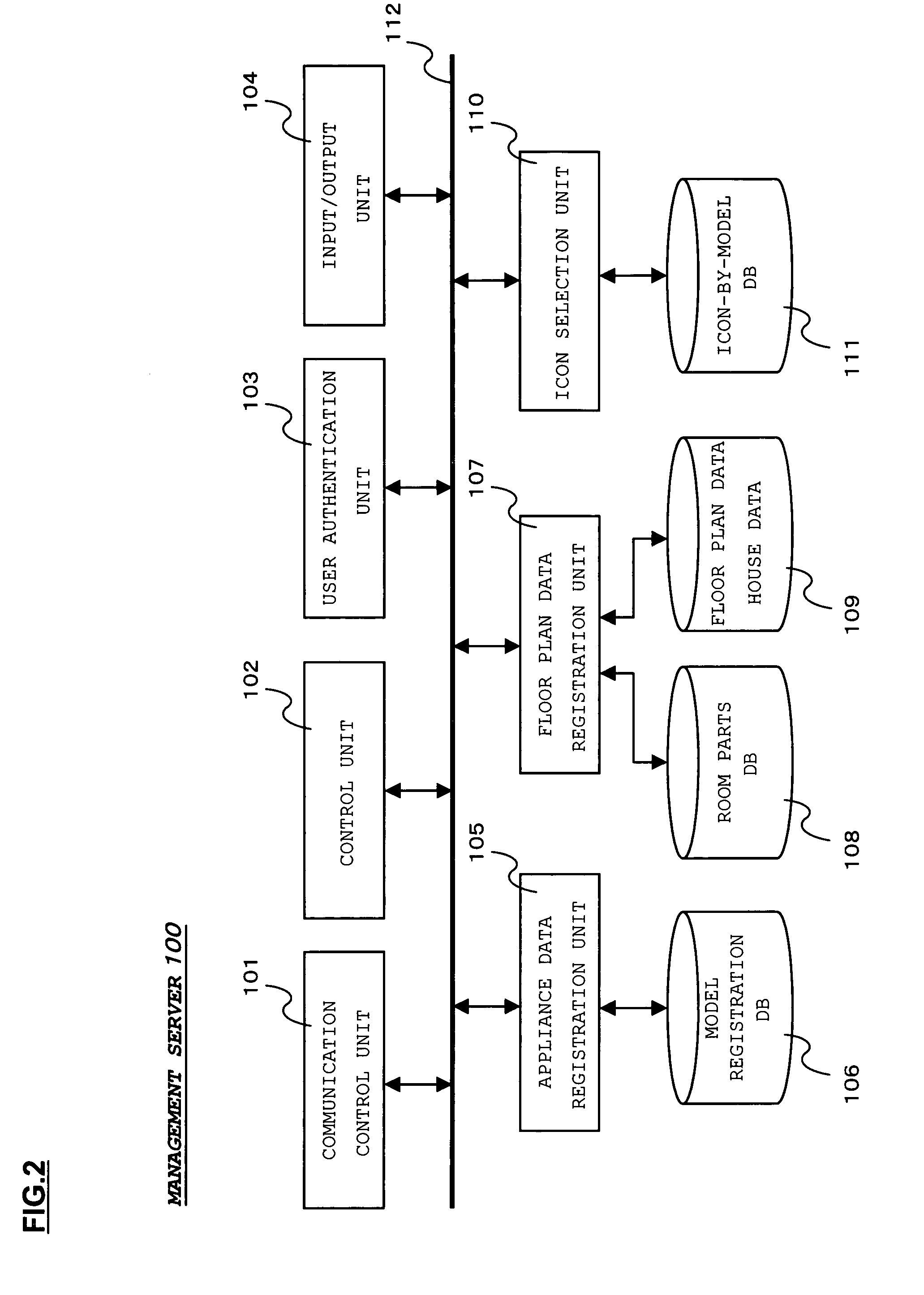
[0086] In the first embodiment, icon information is held on the management server 100 side. However, in this embodiment, icon information is held in the display terminal 200. Thus, in the management server 100, the icon selection unit 110 and the icon-by-model DB are removed from the structure shown in FIG. 2. In addition, in the display terminal 200, a structure necessary for icon display is added to the structure shown in FIG. 6.

[0087]FIG. 11 shows a structure of the display terminal 200 in this embodiment. As shown in the figure, in the display terminal 200 according to this embodiment, an icon selection unit 210 and an icon-by-model DB 211 are added compared with the structure shown in FIG. 6.

[0088] Here, as shown in FIG. 12, table information consisting of a classification of an appliance and a Data Name of icon image information and an icon image information group (contents) corresponding to each Data Name are stored in the icon-by-model DB 211.

[0089] The icon selection unit...

second embodiment

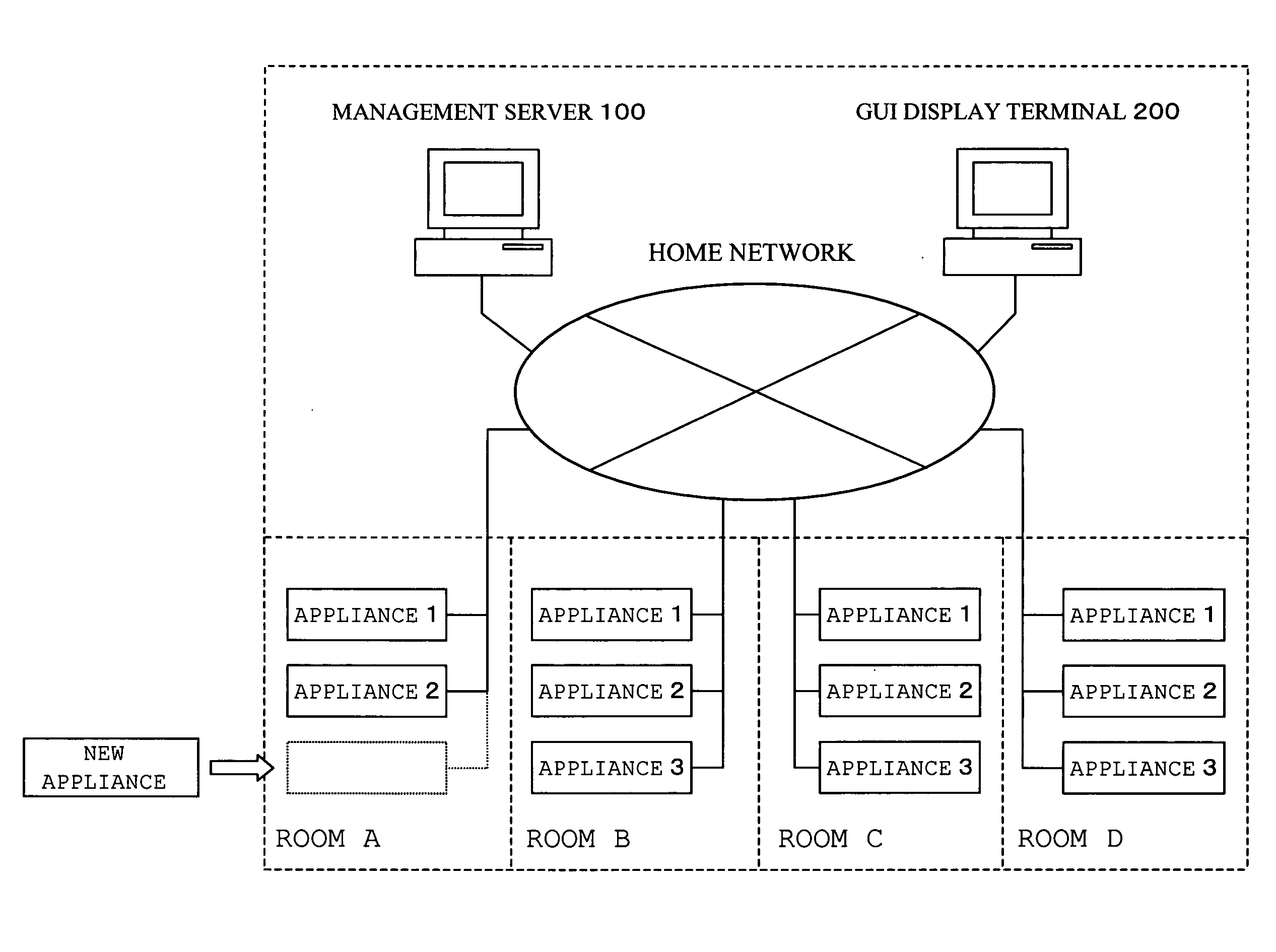
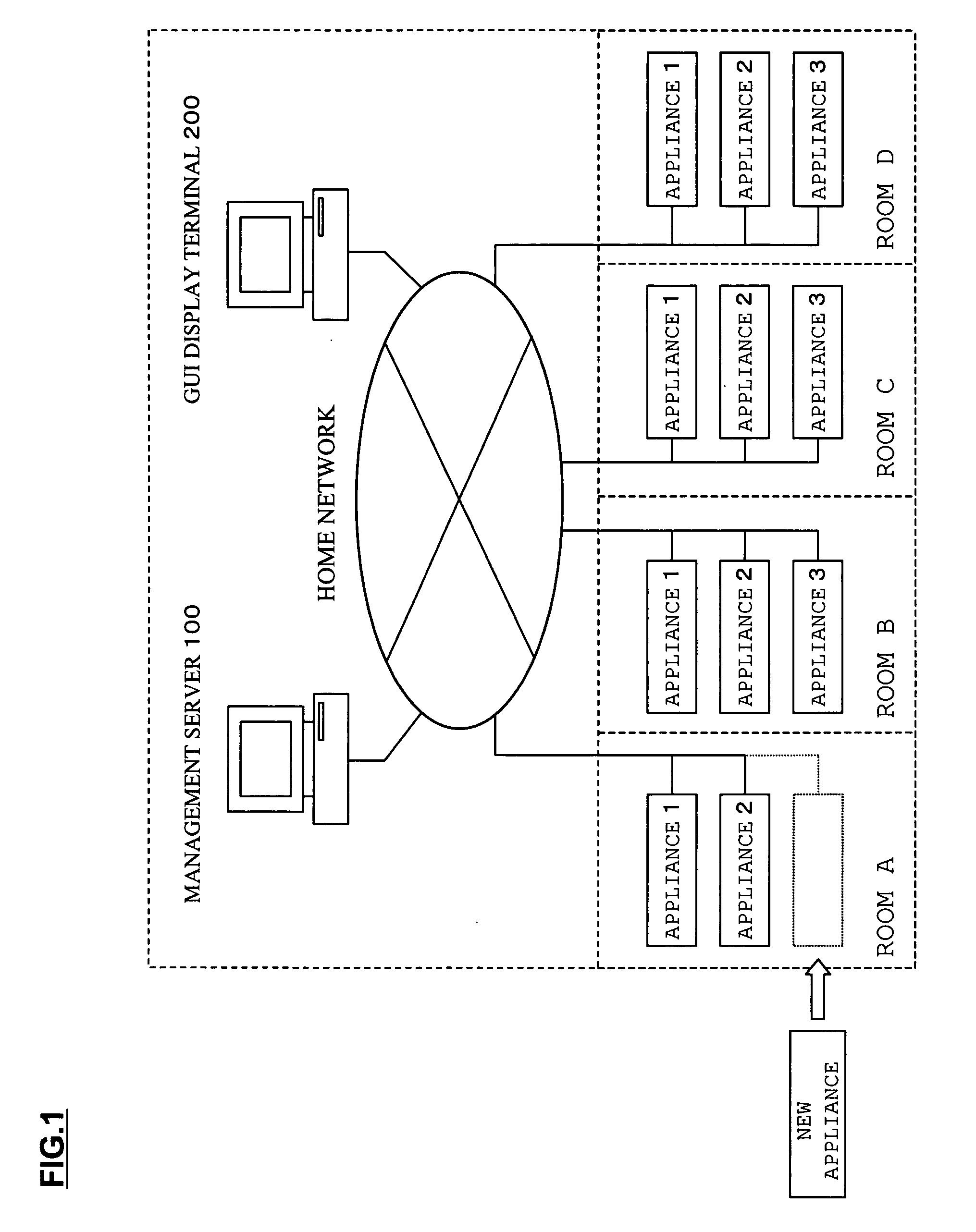
[0095] When a new appliance is connected to the home network, icon image information is acquired as in the first or the second embodiment, and a corresponding appliance icon is displayed in a newly connected appliance area. When a user moves (drags) an appliance icon to a corresponding room, a room No. of a moving destination room is acquired as information on an installation position. Then, this room No. is transmitted to the management server 100 from the display terminal 200 as positional information and registered in the model registration DB 106 in the management server 100.

[0096] According to this embodiment, since only a room No. is registered as installation position information of an appliance, it is possible to simplify contents of data stored in each DB and also simplify display processing. However, since positional information is only the room No., there is also an inconvenience that fine control corresponding to a position in a room cannot be performed.

[0097] The embod...


PUM


Abstract

When an appliance is connected to the home network, appliance information is transmitted to a display terminal from the appliance. The display terminal transmits the received appliance information to a management server and requests the management server to transmit appliance icon information of the appliance. The management server extracts icon information conforming to the received appliance information from an icon database and sends the icon information to the display terminal. The display terminal generates an appliance icon image from the acquired icon information and superimposes and displays the appliance icon image on a floor plan image of a house. When a user moves the appliance icon to an installation location on a display screen, a room No. of a moving destination and an installation position in the room are detected. The detected positional information is sent to the management server and registered in association with the appliance.

Description

BACKGROUND OF THE INVENTION [0001] 1. Field of the Invention [0002] The present invention relates to a network apparatus and a program product, and more particularly to a network apparatus and a program product preferably used in registering positional information of an appliance connected to a network. [0003] 2. Description of the Related Art [0004] In recent years, a so-called home networking system for controlling home appliances via a home network has been proposed and standardized. In this system, a controller such as a home server is connected to a home network. This controller transmits a control command to control an object apparatus. [0005] Here, communication between the controller and the home appliances is performed using a communication protocol such as ECHONET, UPnP, or SCP. A power supply line or the like for supplying power to the respective home appliances is used as a communication network. In other words, the home appliances and the controller are connected to the...

Claims


Application Information

Patent Timeline
Patent Type & Authority Applications(United States)
IPC IPC(8): G06F15/16H04L12/28
CPCH04L12/2803H04L12/281H04L12/2807
Inventor OGAWA, KAZUYAYAMADA, KENHIRATA, TOSHIYUKIHATAYAMA, YOSHINORI
Owner SANYO ELECTRIC CO LTD
Why Eureka
Try Eureka