Air vent for liquid containers, based on the principle of communicating vessels

a technology of communicating vessels and air vents, which is applied in the direction of liquid dispensing, containers, bottles, etc., can solve the problems of generating a substantial increase of manufacturing cost, inconvenient operation, and inability to meet the needs of customers,

Inactive Publication Date: 2005-06-23
CARVALHO DAVID DE
View PDF23 Cites 17 Cited by
  • Summary
  • Abstract
  • Description
  • Claims
  • Application Information

AI Technical Summary

Problems solved by technology

In those cases, the flow is usually not uniform (gushes), and very often the container is also pressed to improve the outlet flow; however, this very often ends up making the product come out in an excess through the spout and the product may also come out through the air vent just like in olive oil containers, for instance.
This system undoubtedly improves the functioning of the baby bottle significantly; however, its industrial feasibility is complex and generates a substantial increase of the manufacturing cost, since the functioning ends up being equally as complex and requiring special cleaning care, besides the fact that the parts are disposable (membrane).
Although this type of baby bottle is constructed in a particular way and functions excellently, it requires a series of special care; in other words: it does not enable any sudden changes in handling (shaking, etc .
. . ) since in that case and in other similar ones leakage may occur through the air vent; the air is only sent to the bottom of the bottle after the baby starts sucking so that the vacuums forms at the bottom of the bottle and therefore, at the beginning, the milk located in the tube goes to the bottom of the bottle; also this type of air vent does not allow for the bottle to be warmed up in a bain-marie.

Method used


Image

  • Air vent for liquid containers, based on the principle of communicating vessels
  • Air vent for liquid containers, based on the principle of communicating vessels
  • Air vent for liquid containers, based on the principle of communicating vessels

Examples


Embodiment Construction

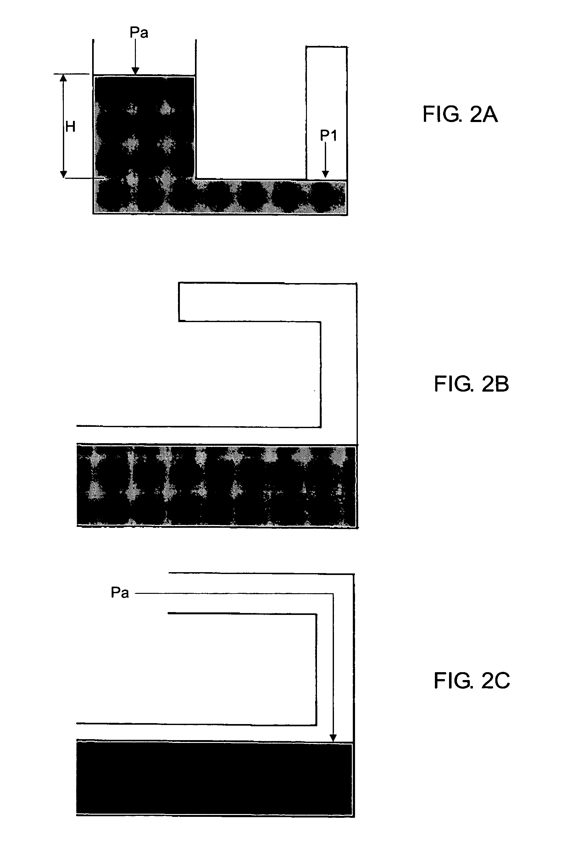
[0065] As previously mentioned, this invention is based on the principle of communicating vessels and on the balance of pressures.

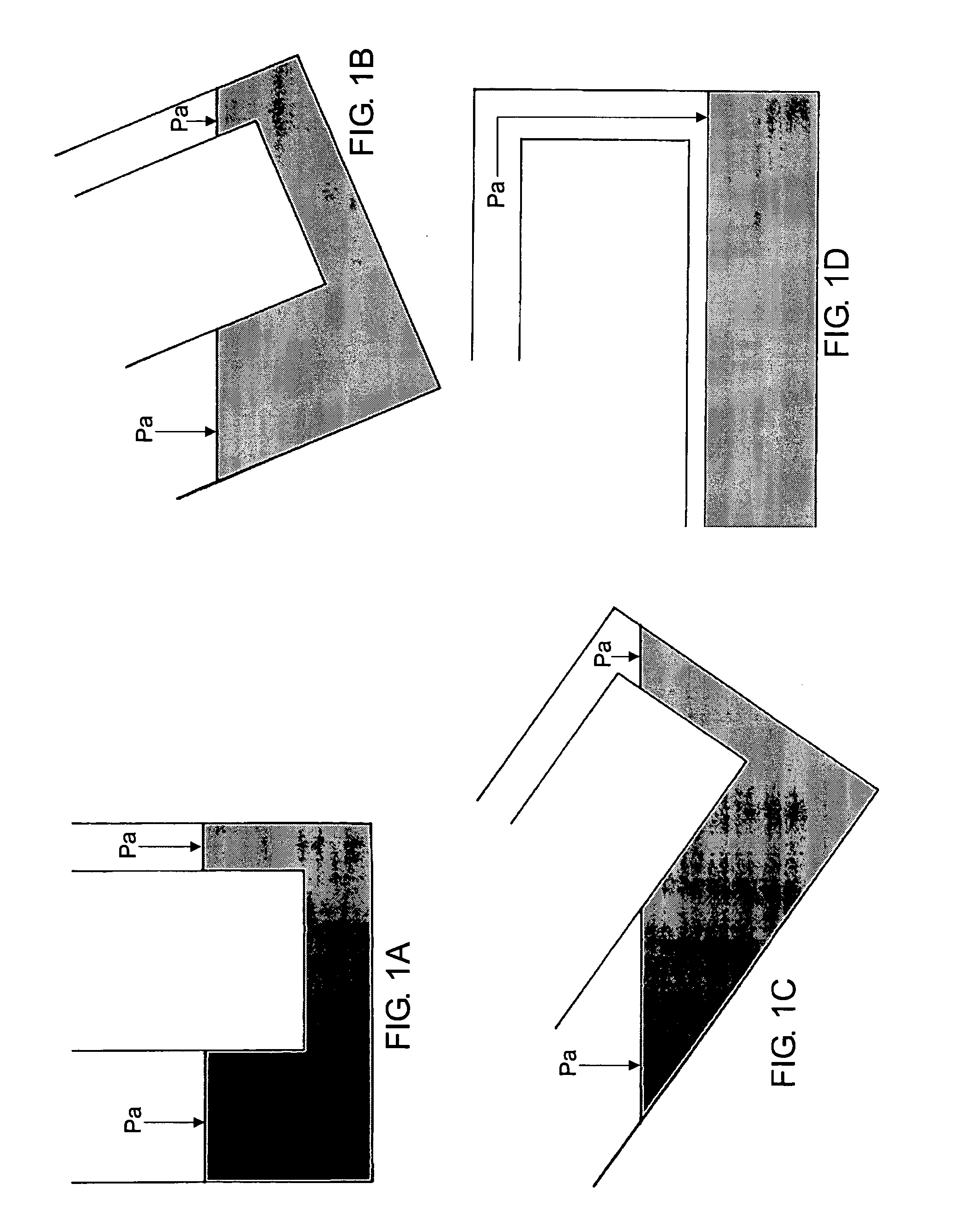
[0066] The principle of communicating vessels establishes that: “The levels of liquid in two adjacent vessels are the same provided the pressure on those levels is the same.” (FIG. 1A).

[0067] Due to that, when communicating vessels are tilted and the same pressure is maintained on the levels of both vessels (the atmospheric pressure usually), those levels are kept in a horizontal position so that the vessel placed above is emptied of its liquid when both vessels are almost horizontal (FIG. 1C). The horizontal position ensures that the upper vessel will be emptied of any liquid (FIG. 1D). The horizontal position is reached before the tilted position (lower vessel container turned downwards); this is when the liquid outflow starts in the lower vessel. Therefore, at the beginning of the liquid outflow of the lower vessel, external air is already going to t...


PUM


Abstract

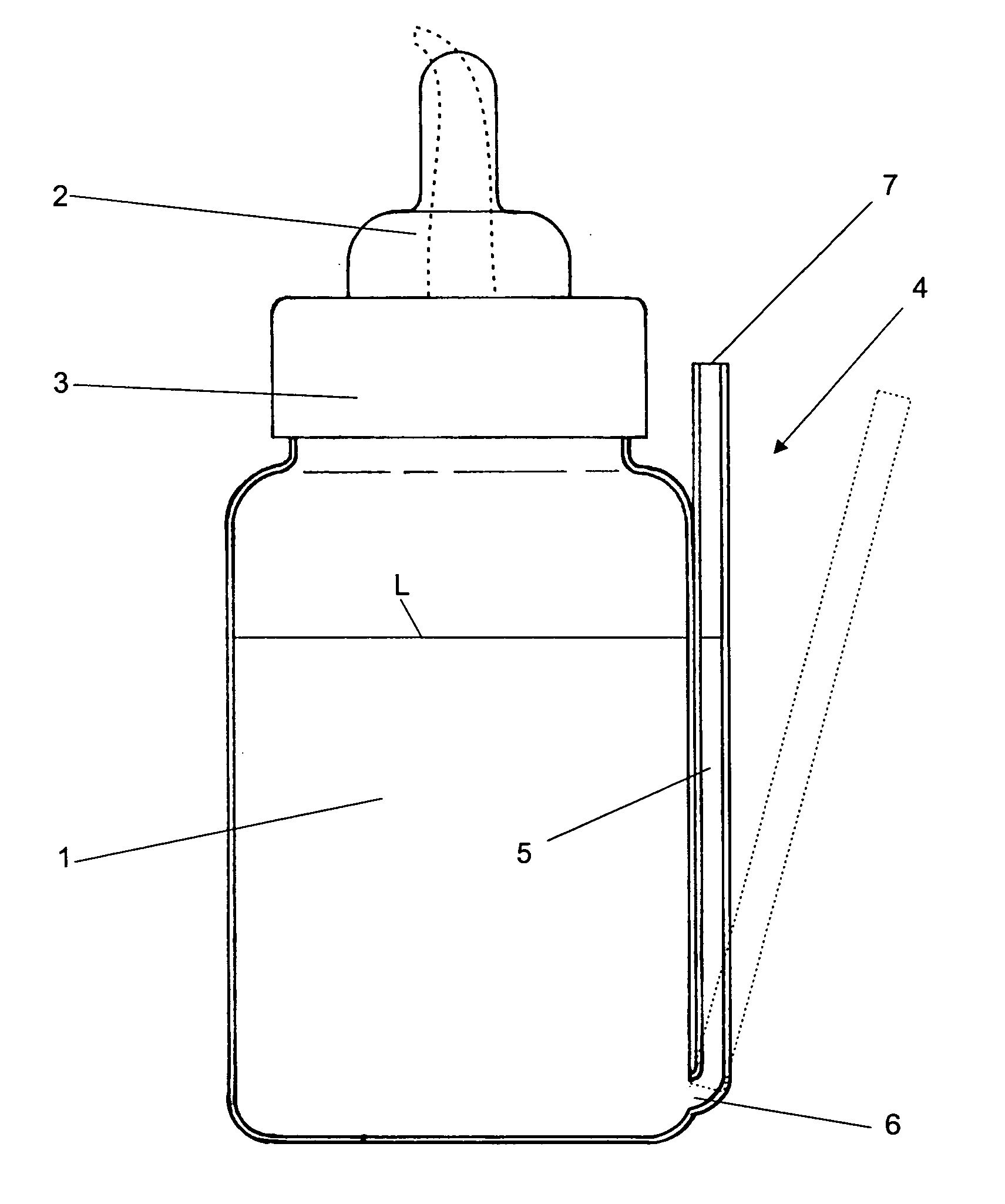
AIR VENT FOR LIQUID CONTAINERS BASED ON THE PRINCIPLE OF COMMUNICATING VESSELS, developed to be used in different types of containers, i.e. baby bottles, flask, or other similar recipients (1) for the conditioning of any liquid easily poured through the upper spout (2) combined with any type of lid (3) to close the aforesaid flask (1); which also may be manufactured using any kind of material, as also it is considered upper spout (2) any outlet for the liquid inside the flask or container (1), where this spout can have the characteristics known to a nipple or a hard plastic spout or even a metal spout, as those used in olive oil cans, be they retractile or not, such container (1) includes an air vent (4), defined by a system based on the principle of communicating vessels and in the balance of pressures, defined by a duct of an adequate diameter (5) placed in a vertical or oblique manner, whose lower end (6) is placed inside and in the bottom of the flask (1), while the upper end (7) completely open, is placed outside and at about the height of the lid (3), where the mentioned end configures external air inlet to the bottom of the flask or lower end (6), when the aforesaid flask is sufficiently poured, so that the liquid inside the duct or air vent tube (5) may go to the bottom of the container, enabling the free flow of external air from the entrance (7) to the bottom of the container (6), without passing through the liquid (L) and blocking the formation of vacuum in the bottom of the container (1), before even this same liquid be discharged or sucked from the container (1).

Description

FIELD OF INVENTION [0001] The present invention refers more particularly to the technical and functional enhancements especially created to characterise the means that significantly improve the use and the functioning of liquid containers. For this purpose, this invention defines an air vent or communicating means of an air inlet, adaptable to liquid containers whose body may be rigid, quasi-rigid or flexible, whereby the function of such an air vent aims at avoiding the formation of vacuum at the bottom of the container at the beginning, and during the discharge of liquid; logically, the neutralisation of the vacuum is obtained by the fact that the above mentioned air vent enables external air to be sent directly to the bottom of the container before the beginning of the discharge or of the liquid suction; and, this air flow does not even go through the liquid discharged, which thus provides different technical effects that are beneficial for the functioning of the entire set. [000...

Claims


Application Information

Patent Timeline
Patent Type & Authority Applications(United States)
IPC IPC(8): A61J9/04B65D23/04B65D47/32B67D7/08
CPCB65D47/32A61J9/04Y10S215/902
Inventor CARVALHO, DAVID DE
Owner CARVALHO DAVID DE
Why Eureka
Try Eureka