Novel thermal circulation system

A thermodynamic cycle system, a new type of technology, applied in the direction of steam engine devices, machines/engines, mechanical equipment, etc., can solve the problems of intermittent system work and low thermal efficiency

Active Publication Date: 2009-10-21
福建省创隆电器科技有限公司
View PDF2 Cites 13 Cited by
  • Summary
  • Abstract
  • Description
  • Claims
  • Application Information

AI Technical Summary

Problems solved by technology

[0006] The purpose of the present invention is to solve the problem that in the thermodynamic cycle system, the medium needs external power to return from low pressure to high pressure, the system needs to be interrupted, and the thermal efficiency is low. It provides a series or parallel connection of multiple liquid storage devic

Method used


Image

  • Novel thermal circulation system
  • Novel thermal circulation system

Examples


Embodiment 1

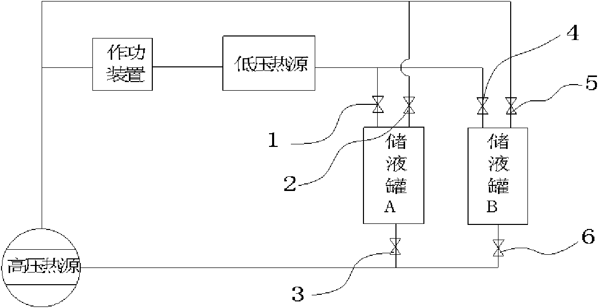
[0018] Embodiment one, such as figure 1 As shown, the parallel circulation system, the system is in the initial state, the stop valve five (5), the stop valve one (1), the stop valve six (6) are closed, and the stop valve four (4), the stop valve two (2), Stop valve three (3), after a period of time, close stop valve two (2) and stop valve three (3), let the liquid storage tank A cool naturally, after the high-pressure heat source, that is, the high-pressure generator is heated, the medium pressure rises, and the inside of the pipe A high-pressure, high-speed airflow is formed.

[0019] The high-pressure and high-speed air flows through the working device, that is, the energy conversion device, to the low-pressure end. After passing through a low-pressure heat source such as a cooling refrigerator, the medium enters the liquid storage tank B in a liquid state. When the liquid volume of the liquid storage tank B reaches a certain amount, the cut-off is opened. Valve five (5), ...

Embodiment 2

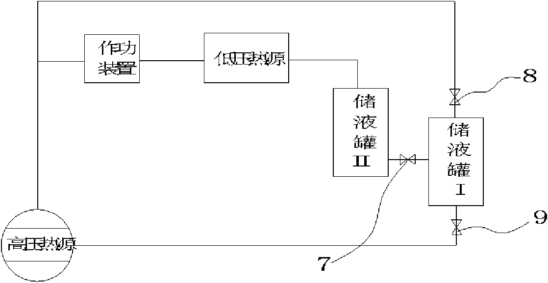
[0021] Embodiment two, such as figure 2 As shown, the initial position of the system is that stop valve eight (8) and stop valve nine (9) are closed, and stop valve seven (7) is opened. After the high-pressure generator is heated, the pressure of the medium rises, and a high-pressure and high-speed airflow is formed in the pipe, and the airflow passes through to do work. The energy conversion of the device reaches the low-pressure heat source. After cooling the refrigerator, the medium becomes liquid. The liquid medium enters the liquid storage tank II and finally reaches the liquid storage tank I. When the liquid medium in the liquid storage tank I reaches the set amount, it is closed. Stop valve seven (7), now open stop valve eight (8) and stop valve nine (9), liquid storage tank I and high-pressure generator pressure balance, also because of the difference in the specific gravity of the liquid medium due to the presence of terrain position height difference, medium Return ...


PUM


Abstract

The invention relates to a thermal circulation technology, in particular to a novel thermal circulation system which adopts a plurality of liquid storage devices connected in series or in parallel so as to achieve the object of repeatedly using the clean energy resource continuously and effectively. The novel thermal circulation system is characterized in that the system is internally provided with more than two liquid storage devices and more than one pipelines with the high pressures and low pressures communicated with each other; the high pressure balance is adopted inside the system; and the liquid medium flows from the low pressure end to the high pressure end by the communicating vessel principle and the terrain position height difference at which the liquid medium of heat energy conversion is stored or the specific weight ratio of the liquid medium.

Description

technical field [0001] The invention relates to thermodynamic cycle technology, in particular to a novel thermodynamic cycle system that adopts multiple liquid storage devices connected in series or in parallel to achieve uninterrupted, high-efficiency, and clean energy that can reuse low-grade heat sources. Background technique [0002] As we all know, a heat engine has two heat sources, high and low temperature. High temperature is generally accompanied by high pressure, and low temperature is accompanied by low pressure. The medium returns from low pressure to high pressure, usually requiring external force. There are many kinds of thermodynamic circulation systems in the prior art, and each has its own characteristics according to different uses and occasions. [0003] For example, the application number is ZL 200510035793.1, a thermodynamic cycle that converts heat energy into useful work. The process is that the gaseous working medium in the initial state becomes exhau...

Claims


Application Information

Patent Timeline
IPC IPC(8): F01K27/00
Inventor 顾功建
Owner 福建省创隆电器科技有限公司
Why Eureka
Try Eureka