Measurement connector for test device

a technology for measuring devices and connectors, applied in the direction of data switching networks, coupling device connections, instruments, etc., can solve the problems of network cabling failing certification, requiring repair or replacement, additional expense and frustration, etc., to minimize the interaction of electromagnetic fields

Inactive Publication Date: 2005-06-23
AVO MULTI AMP CORP MEGGER
View PDF8 Cites 2 Cited by
  • Summary
  • Abstract
  • Description
  • Claims
  • Application Information

AI Technical Summary

Benefits of technology

[0015] In some aspects, the distance determined using an inductance component associated with the first biased contact and a capacitance component related to the distance between the first and second biased contacts to achieve a desired impedance related to an impedance of the at least first channel of the local area network cabling. In one aspect, the connector assembly is operable to test network cabling having a second channel. In this aspect, the connector system further includes a third and fourth biased contacts coupled to the circuit board circuitry that communicates with the second channel of the local area network cabling such that the third and fourth biased contacts are positioned relative to the first and second biased contacts to minimize the interaction of an electromagnetic field generated by the first and second biased contacts and an electromagnetic field generated by the third and fourth biased contacts.

Problems solved by technology

Network adapters that the device employs to connect the measurement device to the network, however, may introduce communication errors in otherwise accurate signal, which cannot be separated from the local areas network cabling.
In this instance, the network cabling would fail the certification and require repair or replacement, when in fact the adapter connecting the device to the wall jack of the network was actually the cause of the errors.
Unfortunately, measurement test devices routinely incorporate off-the-shelf adapters, which are inadequate for these purposes and cause inefficiencies, additional expense and frustration for those desiring to certify the local area network cabling.

Method used


Image

  • Measurement connector for test device
  • Measurement connector for test device
  • Measurement connector for test device

Examples


Embodiment Construction

[0026] It should be understood at the outset that although an exemplary implementation of one embodiment is illustrated below, the present system may be implemented using any number of techniques, whether currently known or in existence. The present disclosure should in no way be limited to the exemplary implementations, drawings, and techniques illustrated below, including the exemplary design and implementation illustrated and described herein, but may be modified within the scope of the appended claims along with their full scope of equivalents.

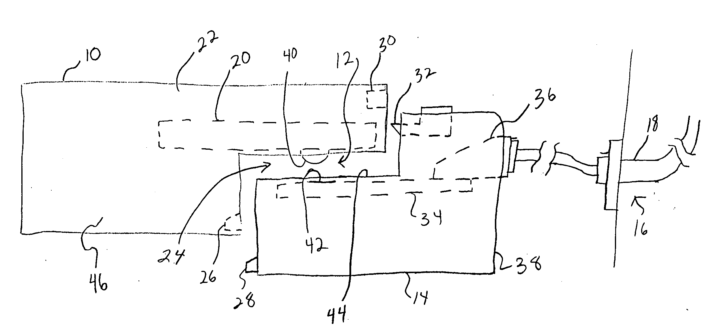
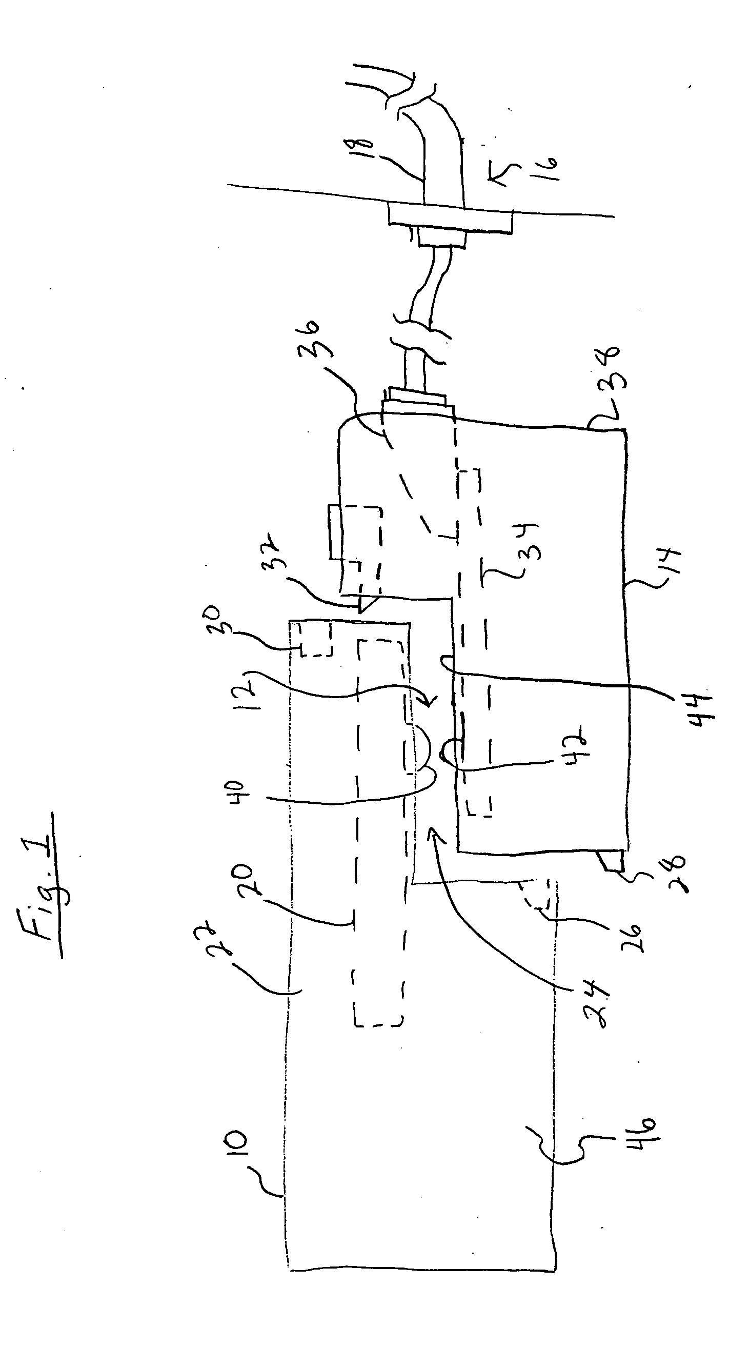
[0027]FIG. 1 is a side-view illustrating a device 10 employing a connector assembly 12 for coupling to an adapter 14 connectable a network 16. The device 10 may be a measurement or test device, such as a local area network certification test device for certifying cabling 18 of the network 16. The device 10, in other embodiments, is a computer, peripheral, network appliance or other device usefully employing an adapter 14 for connection to...


PUM


Abstract

A measurement connector for connecting a device to testing network cabling is provided. The device includes a device housing having a coupling portion and a test module retained by the device housing and having circuitry to promote testing of a channel of the network cabling. A biased connector extends from the device housing and communicates with the circuitry of the test module. An adapter housing is configured to couple with the coupling portion of the device housing. A mating portion promotes connection to the network cabling and is coupled to the adapter housing. A contact communicates with the mating portion and is coupled to the adapter housing such that the biased connector contacts the contact when the adapter housing is coupled to the device housing.

Description

CROSS-REFERENCE TO RELATED APPLICATIONS [0001] None. STATEMENT REGARDING FEDERALLY SPONSORED RESEARCH OR DEVELOPMENT [0002] Not applicable. REFERENCE TO A MICROFICHE APPENDIX [0003] Not applicable. FIELD OF THE INVENTION [0004] This invention relate in general to the field of measurement devices and connectors and more specifically, but not by way of limitation, to a connector for connecting devices, such as a measurement device for testing network cabling, to network cabling via an adapter. BACKGROUND OF THE INVENTION [0005] Information system networks include cabling and adapters for communicating data signals. The cabling and adapters installed in an office or other structure must meet certain standards to verify that the network is working properly in the structure. To certify network cabling, a measurement or test device is connected at one point in the local area network of the structure and a second measurement device is connected at another point in the network. The first me...

Claims


Application Information

Patent Timeline
Patent Type & Authority Applications(United States)
IPC IPC(8): G01R1/04
CPCG01R1/0416H04L43/50H04L12/2697
Inventor BARMETTLER, MARK G.
Owner AVO MULTI AMP CORP MEGGER
Why Eureka
Try Eureka