Radiofrequency magnetic field resonator and a method of designing the same

a radiofrequency magnetic field and resonance technology, applied in the field of magnetic resonance analysis, can solve the problems of affecting the quality of analysis, affecting the design of bird cage coils, and similar limitations, so as to minimize electromagnetic interactions and minimize magnetic field inhomogeneities

Inactive Publication Date: 2007-11-20
RAMOT AT TEL AVIV UNIV LTD
View PDF11 Cites 13 Cited by
  • Summary
  • Abstract
  • Description
  • Claims
  • Application Information

AI Technical Summary

Benefits of technology

[0034]According to still further features in the described preferred embodiments the method further comprising designing an RF shield for minimizing electromagnetic interactions between the RF resonator and at least one gradient coil and / or between the RF resonator and a device for providing a static magnetic field.
[0109]According to still further features in the described preferred embodiments each of the at least two conductive elements has a predetermined capacitance distribution for minimizing effects of an object to be imaged on the magnetic field and for minimizing corona discharge from the at least two conductive elements.

Problems solved by technology

RF resonators are required to generate a very uniform RF magnetic field, as any inhomogeneity in the RF magnetic field causes identical spins at different locations within the imaged object to respond differently to the RF radiation thereby distorting the image or negatively affecting the quality of the analysis.
Conceptually, it is very similar to the conventional solenoid, thus, it suffers from similar limitations as the multi-turn solenoid and it is therefore used only for imaging of particular samples, such as the breast and forearm.
However, as the number of current-modes increases, so does the complexity of the birdcage coil design.
An inherent limitation of the birdcage coil is that in the design process, both the magnetic field characteristic and the resonance characteristic of the birdcage coil are to be simultaneously calculated, as these two characteristics are entangled.
Although this effect can be approximated during simulation, the validity of such approximation is very limited due to the various sizes, structures and orientations that a biological organ may exhibit when placed in the birdcage coil, contrary to the spherical or cylindrical uniform sample that is typically used for simulations.
The additional capacitors break the symmetry of the birdcage coil, result in loosing field homogeneity and introduce non-zero contributions from one or more undesired current-modes.
This coil solves some of the problems associated with the birdcage coil, however its design and manufacturing is still rather complicated.
Hence, for a sufficiently efficient Litz coil the braiding is very complex and ultra thin.
This coil, however, is suitable only for non-imaging applications of small sized samples.
It will be appreciated that, all of the prior art slotted tube resonators suffer from two crucial limitations: (i) the slotted tube resonator fails to provide a mechanism for balancing the RF field homogeneity once it has deviated from its original design due to sample-field interactions; and (ii) the geometrical configuration of the slotted tube resonator is such that the generated RF magnetic field has a linear polarization.
An intrinsic limitation of the linear polarization is the power losses, which are explained by wasted components in the mathematical expansion of the linear polarization.
However, this birdcage coil only partially addresses to problems associated with effects of interaction between the magnetic field and the imaged object.
Specifically, this birdcage coil, although successfully providing a sophisticated circuitry for tuning the resonance characteristics and matching the impedance, fails to provide a satisfactory mechanism for correcting inhomogeneity in the magnetic field once a sample is placed therein.

Method used


Image

  • Radiofrequency magnetic field resonator and a method of designing the same
  • Radiofrequency magnetic field resonator and a method of designing the same
  • Radiofrequency magnetic field resonator and a method of designing the same

Examples


example 1

A Linear RF Resonator

[0201]A prototype of a linear resonator having two conductive elements was designed and built for imaging a rat head in an 8.46 T static magnetic field generated by a AVANCE 360 WB spectrometer, purchased from Bruker Medizintechnik GmbH, D-76275 Ettlingen, Germany.

[0202]Description of the Prototype

[0203]The ratio between the resonator size and the resonance wavelength was selected to be about 0.02, hence, any variation of the RF phase was negligibly small (the so called “near-field approximation”). The mathematical reason for the smallness of variation is that the variation is proportional to the sine of the distance from the conductive element, hence, for distances which are sufficiently smaller than the wavelength, the sine (and the variation) approaches zero. Specifically, the distance from the conductive surfaces to the center of the imaged sample was 1.5 cm and the resonant wavelength was 83.2 cm. For such configuration the change in the wave amplitude over...

example 2

A Quadrature RF Resonator

[0237]Following is a description of a quadrature RF resonator designed as two decoupled linear RF resonators.

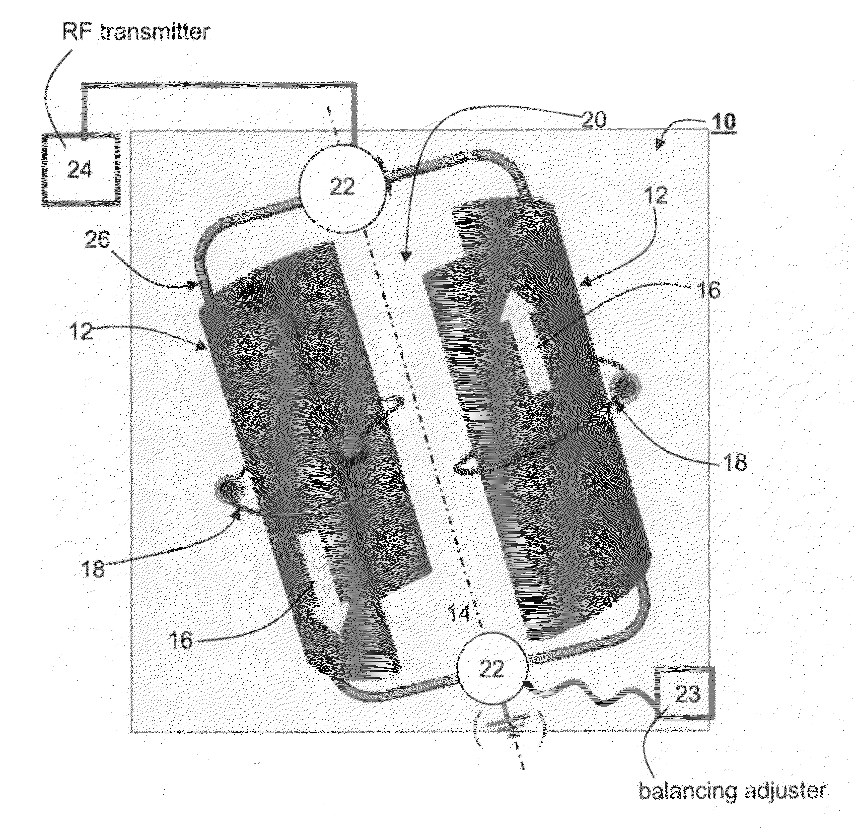
[0238]Reference is now made to FIG. 20 illustrating a top view of the quadrature RF resonator of this example. The quadrature resonator of this example includes four conductive elements arranged as two pairs, designated 12 and 12a. Pair 12 and pair 12a are positioned so that the respective symmetry axes are perpendicular to each other. Antiparallel currents 16 are driven through pair 12 and pair 12a, where, according to the common convention, current which is outgoing downwards (into the plane of FIG. 20) is designated by the cross symbol and current which is incoming upwards is designated by the dot symbol. Currents 16 are driven by a split phase RF source, so that the voltage on pair 12 is shifted by 90° with respect to the voltage on pair 12a.

[0239]Currents 16 generate magnetic field in and outside the volume surrounded by the conductive elements....


PUM


Abstract

A radiofrequency (RF) resonator for magnetic resonance analysis, the RF resonator comprising: (a) at least two conductive elements, each having a first curvature along a direction perpendicular to a longitudinal axis, the at least two conductive elements being spaced along the longitudinal axis, so that when an RF current flows within the at least two conductive elements in a direction of the longitudinal axis, a substantially homogeneous RF magnetic field, directed perpendicular to the longitudinal axis, is produced in a volume defined between the at least two conductive elements. The RF resonator further comprises (b) an electronic circuitry designed and configured for providing predetermined resonance characteristics of the RF resonator, for matching an impedance of the RF resonator to an impedance of an RF transmitter electrically communicating with the electronic circuitry, and for balancing the RF magnetic field to have a substantially symmetrical profile with respect to a transverse axis being perpendicular to the longitudinal axis.

Description

RELATED PATENT APPLICATION[0001]This application is a National Phase Application of PCT / 1L03 / 00826 having International Filing Date of 12 Oct. 2003, which claims priority from U.S. Provisional Patent Application No. 60 / 418,707 filed 17 Oct. 2002 and U.S. Provisional Patent Application No. 60 / 437,452 filed 2 Jan. 2003.FIELD AND BACKGROUND OF THE INVENTION[0002]The present invention relates to magnetic resonance analysis and, more particularly, to a radiofrequency (RF) resonator for generating a substantially homogeneous RF magnetic field for the purpose of magnetic resonance analysis. The present invention further relates to a method of designing the RF resonator, a magnetic resonance imaging (MRI) apparatus incorporating the RF resonator and a method of magnetic resonance analysis of an object.[0003]MRI is a method to obtain an image representing the chemical and physical microscopic properties of materials, by utilizing a quantum mechanical phenomenon, known as Nuclear Magnetic Res...

Claims


Application Information

Patent Timeline
Patent Type & Authority Patents(United States)
IPC IPC(8): G01V3/00G01R33/34G01R33/343
CPCG01R33/343G01R33/34046
Inventor NEUFELD, ARNONLEVIN, MENAHEMNAVON, GIL
Owner RAMOT AT TEL AVIV UNIV LTD
Why Eureka
Try Eureka