Circuit arrangement

a circuit arrangement and circuit technology, applied in the field of circuit arrangement, can solve the problems of complex solution, large processing cost, and non-linearity of capacitance/voltage characteristics of varactors

Active Publication Date: 2005-06-23
APPLE INC
View PDF10 Cites 2 Cited by
  • Summary
  • Abstract
  • Description
  • Claims
  • Application Information

AI Technical Summary

Benefits of technology

[0022] In one embodiment, the voltage controllable oscillator includes a modulator as described hereinabove. This arrangement provides the oscillator with a tuning circuit wherein the frequency of the oscillator can be modulated by a modulation signal independently of the main frequency control signal.
[0023] According to yet another aspect of the present invention, there is provided a tunable radio frequency (RE) circuit comprising: the resonant combination of a tuning varactor, a modulation varactor and an associated inductance, the tuning varactor and the modulation varactor being respectively coupled to a tuning control input and modulation input which are DC isolated from each other.
[0024] The invention also includes a tunable RF circuit including a plurality of varactors connected in parallel with each other and, coupled to the varactors, capacitance control means operable to apply different variable voltages simultaneously across respective varactors.

Problems solved by technology

One problem with varactors is that their capacitance / voltage characteristics are typically very non-linear as shown in FIG. 1a, which illustrates a typical metal oxide semiconductor varactor (MOSvar) capacitance / voltage characteristic.
However, the implementation of a hyper-abrupt varactor requires extra processing during manufacture, which is expensive.
However, this solution is complex, can be physically large, and may be too slow.

Method used


Image

  • Circuit arrangement
  • Circuit arrangement
  • Circuit arrangement

Examples


Embodiment Construction

[0034] Reference now will be made in detail to the presently preferred embodiments of the invention, one or more examples of which are illustrated in the accompanying drawings. Each example is provided by way of explanation of the invention, which is not restricted to the specifics of the examples. In fact, it will be apparent to those skilled in the art that various modifications and variations can be made in the present invention without departing from the scope or spirit of the invention. For instance, features illustrated or described as part of one embodiment, can be used on another embodiment to yield a still further embodiment. Thus, it is intended that the present invention cover such modifications and variations as come within the scope of the appended claims and their equivalents. The same numerals are assigned to the same components throughout the drawings and description.

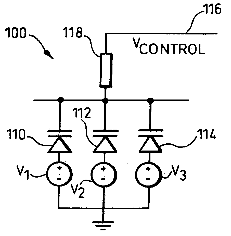
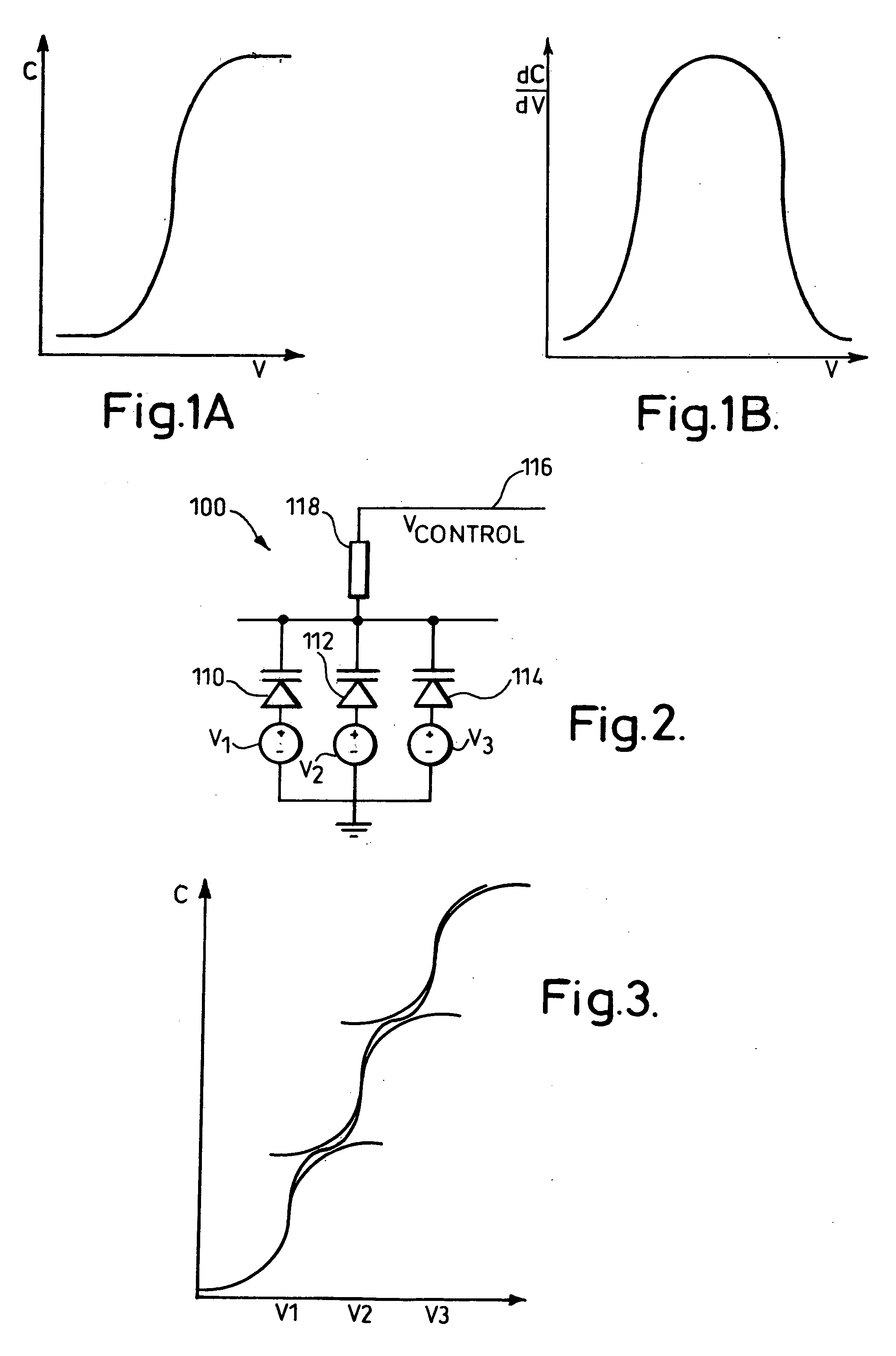
[0035] Referring to FIG. 2, a variable capacitance circuit arrangement 100 has a variable capacitanc...


PUM


Abstract

A circuit arrangement having a plurality of variable capacitance elements such as varactors is described, the varactors having associated electronic control means which controls the capacitance of the variable capacitance elements over a control range. The control range is such that for any particular variable capacitance element a complete variation from a lowest to a highest capacitance is obtained from only a portion of the control range.

Description

CROSS-REFERENCE TO RELATED APPLICATIONS [0001] The present application claims priority to currently pending United Kingdom Patent Application number 0327284.6, filed Nov. 24, 2003. STATEMENT REGARDING FEDERALLY SPONSORED RESEARCH OR DEVELOPMENT N / A BACKGROUND OF THE INVENTION [0002] Varactors are commonly used in RF circuits for tuning oscillators, filters and amplifiers. [0003] One problem with varactors is that their capacitance / voltage characteristics are typically very non-linear as shown in FIG. 1a, which illustrates a typical metal oxide semiconductor varactor (MOSvar) capacitance / voltage characteristic. The non-linear feature of the MOSvar is emphasized by FIG. 1b which shows the first derivative dC / dV of the curve of FIG. 1a. [0004] One device allowing a capacitance / voltage characteristic having an acceptable tuning range and a more linear range to be obtained is a hyper-abrupt varactor. However, the implementation of a hyper-abrupt varactor requires extra processing during ...

Claims


Application Information

Patent Timeline
Patent Type & Authority Applications(United States)
IPC IPC(8): H03J3/18
CPCH03J3/185H03H5/12
Inventor PERRY, COLIN LESLIEPARRY, STEPHEN JOHNDEIDDA, ALESSANDRO F.SHEPHERD, CHRISTOPHER R.
Owner APPLE INC
Why Eureka
Try Eureka