[0012]To achieve the above objects and others, there is provided another apparatus for recording a high resolution video signal having a key input unit for selecting between a high resolution recording mode and a normal recording mode; a low-pass filter for separating a luminance signal from the video signal; an FM modulation unit for receiving the separated luminance signal from the low-pass filter, and modulating the signal frequency by setting a frequency deviation of 3.4 MHZ˜4.4 MHz for a National Television Standards Committee (NTSC) signal and a frequency deviation of 3.8 MHZ˜4.8 MHz for a phase alternation line (PAL) signal or sequential couleur avec memoire (SECAM) signal in a normal recording mode, and by setting a frequency deviation of 3.4+α MHz˜4.4+α MHz for an NTSC signal and 3.8+α MHz˜4.8+α MHz for a PAL or SECAM signal, in which a is a positive number, in a high resolution mode; a recording equalizing unit for receiving the FM-modulated signal from the FM modulation unit, and setting a peaking frequency higher in the high resolution recording mode than a peaking frequency of the normal recording mode to compensate for the frequency characteristics of the luminance signal.
[0013]To achieve the above objects and others, there is provided an apparatus for reproducing a high resolution video signal having a key input unit for selecting between a high resolution reproducing mode and a normal reproducing mode corresponding to a recording mode; a pre-amplifier for amplifying a video signal detected by a video head; a color killer decision unit for generating a color killer control signal when the unit decides the absence of a color signal after determining whether a color signal is present in the video signal output from the pre-amplifier; a reproducing equalizing unit for receiving the video signal output from the pre-amplifier, and then peaking a predetermined frequency signal cutting-off a frequency down-converted color signal frequency band if the color killer control signal is not generated, and not cutting-off a frequency down-converted color signal frequency band if the color killer control signal is generated; a demodulation unit for receiving the input signal from the reproducing equalizing unit, and then frequency-demodulating the input signal to a carrier-wave frequency corresponding to the high resolution or normal reproducing mode; and a low-pass filter unit for receiving the FM-demodulated signal from the demodulation unit, and passing a low band frequency signal lower than a cut-off frequency by setting the cut-off frequency higher than at least a color signal sub-carrier frequency if the color killer control signal is generated, and otherwise by setting the cut-off frequency lower than a color signal sub-carrier frequency.
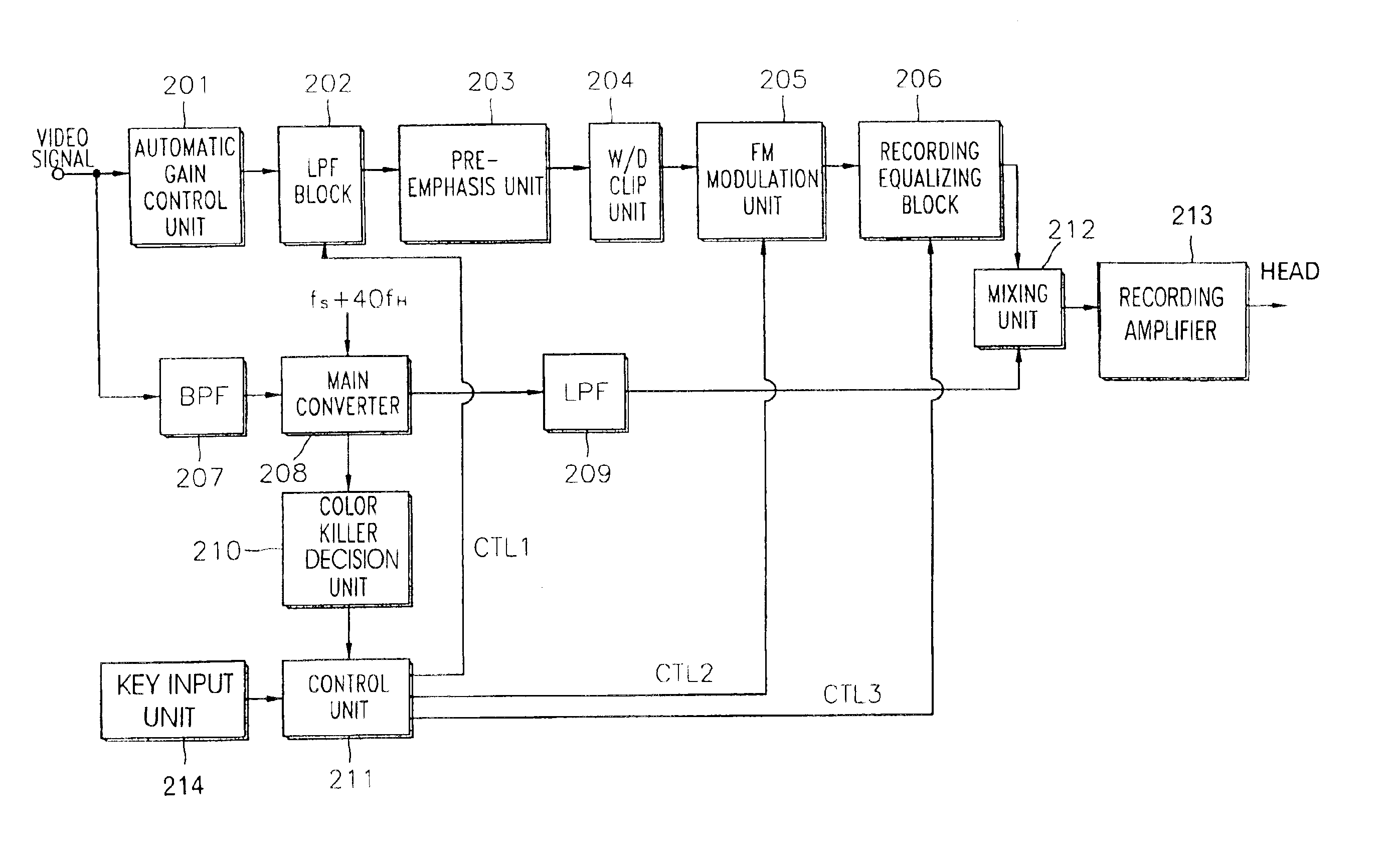
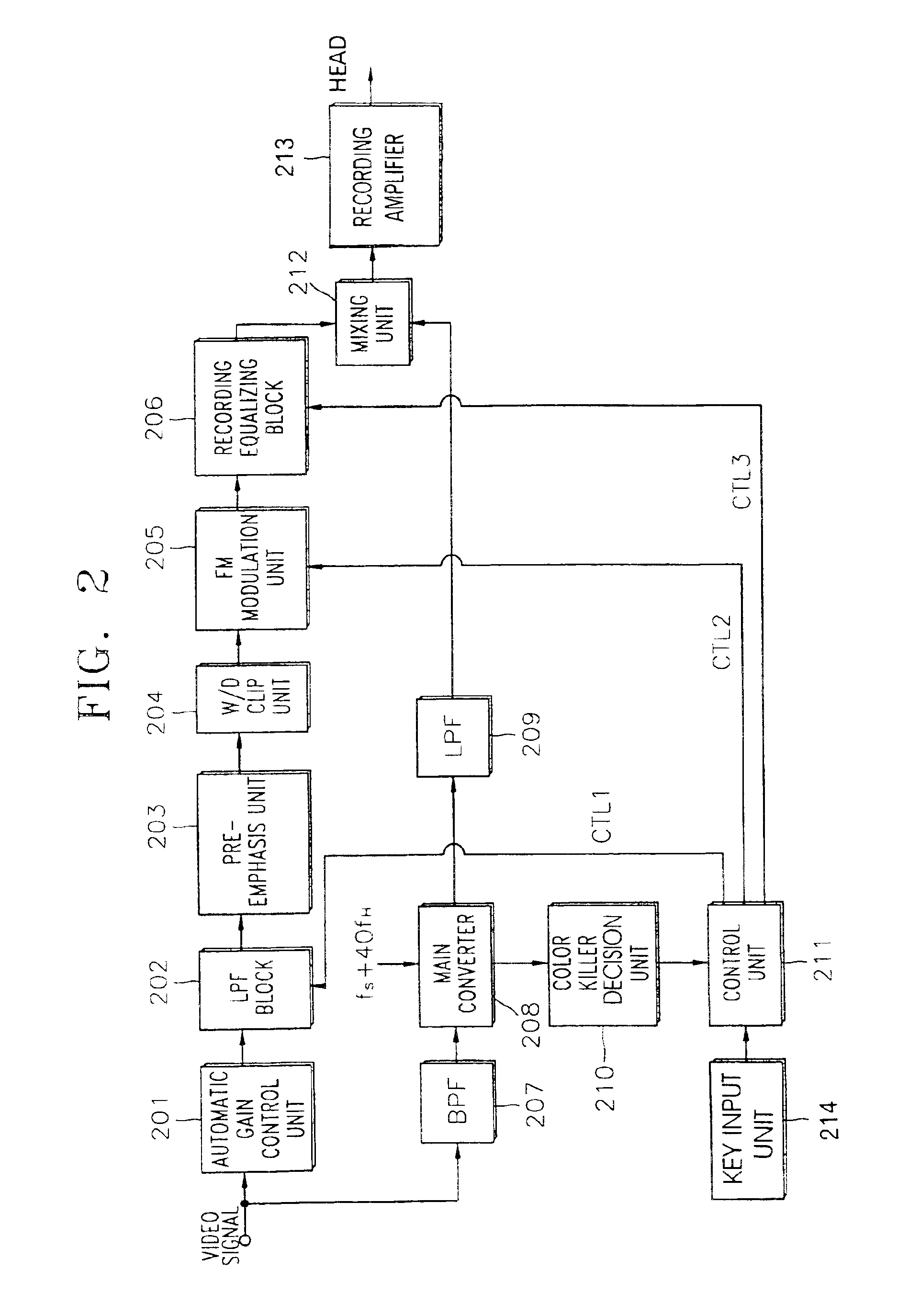
[0014]To achieve these and other objects in accordance with the principles of the present invention, as embodied and broadly described, the present invention provides an apparatus, comprising: a decision unit detecting when a video signal includes a color signal, detecting when said color signal has predetermined characteristics, generating a color killer control signal when said video signal does not include said color signal; a low pass filter unit receiving said video signal, outputting a low frequency band signal, said low frequency band signal being lower than a first cut off frequency by setting said first cut off frequency higher than at least a color signal sub-carrier frequency when said color killer control signal is generated, said low frequency band signal being lower than a second cut off frequency by setting said second cut off frequency lower than a color signal sub-carrier frequency when said color killer control signal is not generated; a frequency modulation unit frequency-modulating said band signal output from said low pass filter unit; and a recording equalizing unit receiving said frequency modulated signal, peaking a predetermined luminance signal frequency band cutting off the frequency down-converted color signal frequency band when said color killer control signal is not generated, and not cutting off the frequency down-converted color signal frequency band when said color killer control signal is generated.
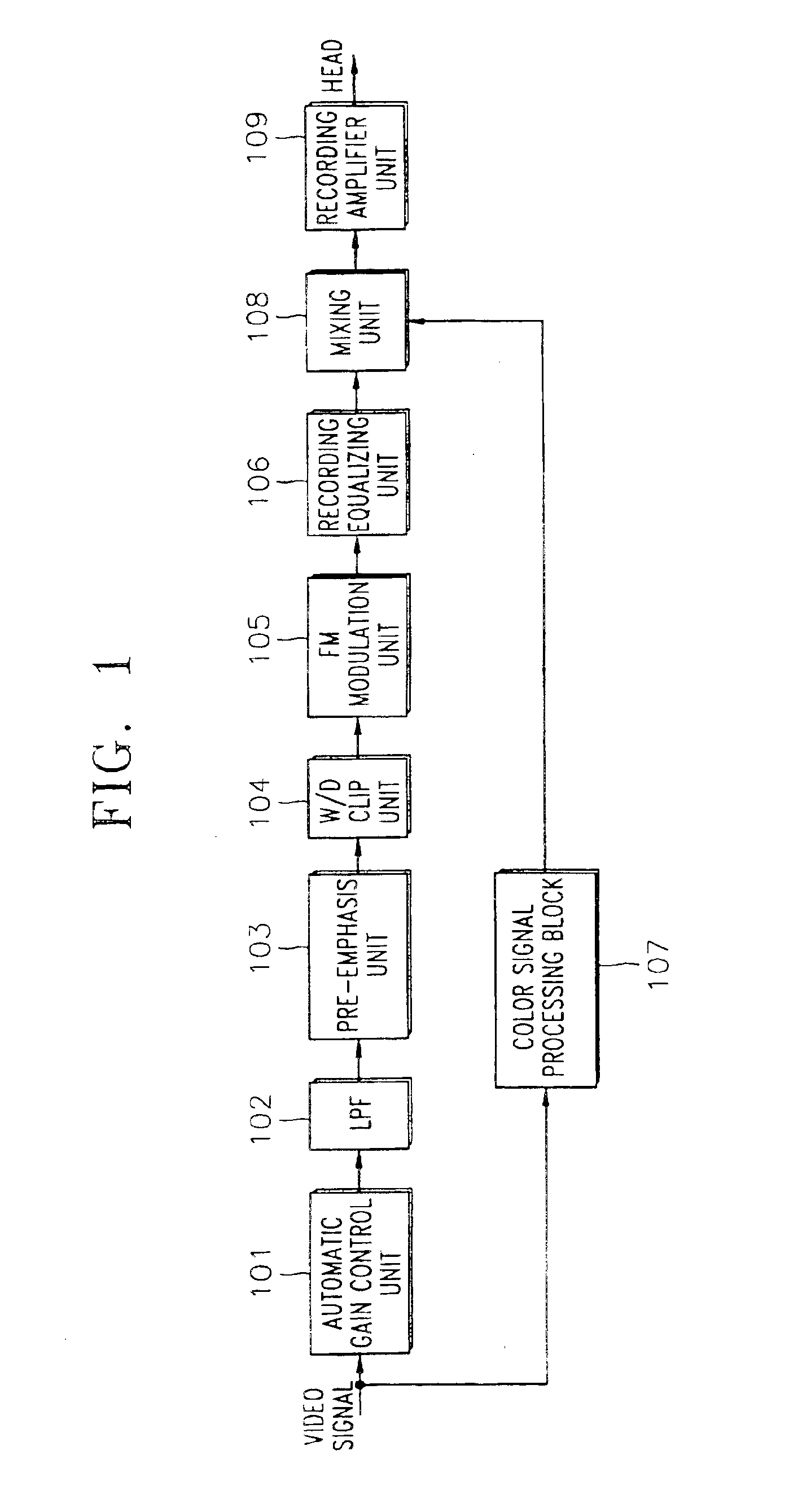
[0015]To achieve these and other objects in accordance with the principles of the present invention, as embodied and broadly described, the present invention provides an apparatus, comprising: a key input unit selecting one mode from among a high resolution recording mode and a normal recording mode; a low pass filter separating a luminance signal from a video signal; a frequency modulation unit receiving said separated luminance signal from said low pass filter, modulating signal frequency by setting a first frequency deviation when said normal recording mode is selected, modulating signal frequency by setting a second frequency deviation when said high resolution recording mode is selected; a recording equalizing unit receiving said frequency modulated signal from said frequency modulation unit, setting a first peaking frequency when said high resolution recording mode is selected, setting a second peaking frequency when said normal recording mode is selected, said first peaking frequency being higher than said second peaking frequency.
[0016]To achieve these and other objects in accordance with the principles of the present invention, as embodied and broadly described, the present invention provides an apparatus, comprising: a key input unit selecting one reproducing mode from among a high resolution reproducing mode and a normal reproducing mode, said selected reproducing mode corresponding to a recording mode; a pre-amplifier amplifying a video signal; a color killer decision unit generating a color killer control signal when no color signal is present in said video signal output from said pre-amplifier; a reproducing equalizing unit receiving said video signal output from said pre-amplifier, peaking a predetermined frequency signal cutting-off a frequency down-converted color signal frequency band when said color killer control signal is not generated, and not cutting-off a frequency down-converted color signal frequency band when said color killer control signal is generated; a demodulation unit receiving a first signal output from said reproducing equalizing unit, frequency-demodulating said first signal to a carrier-wave frequency corresponding to said selected reproducing mode; and a low-pass filter unit receiving said frequency modulated-demodulated signal from said demodulation unit, passing a low band frequency signal lower than a first cut-off frequency by setting said first cut-off frequency higher than at least a color signal sub-carrier frequency when said color killer control signal is generated, passing a low band frequency signal lower than a second cut-off frequency by setting said second cut-off frequency lower than a color signal sub-carrier frequency when said color killer control signal is not generated.
[0017]The present invention is more specifically described in the following paragraphs by reference to the drawings attached only by way of example. Other advantages and features will become apparent from the following description and from the claims.

