Apparatus and method for controlling a cryogenic cooling system

Active Publication Date: 2014-09-04
OXFORD INSTR NANOTECH TOOLS
View PDF11 Cites 10 Cited by
  • Summary
  • Abstract
  • Description
  • Claims
  • Application Information

AI Technical Summary

Benefits of technology

[0007]We have realised that it is possible to improve the cooling efficiency of the mechanical refrigerator by careful control of the frequency of the cyclical gas pressure which is used to operate the mechanical refrigerator. We have also realised that the pressure in one or each of the supply or return gas lines when connected to an operational compressor can be used to provide feedback upon the operational status of the mechanical refrigerator which changes as such a refrigerator undergoes a cooling cycle. With knowledge of how the pressure response of the mechanical refrigerator provides information about the stage of the cooling cycle (for example the temperature achieve

Problems solved by technology

Cryogenic liquids have associated disadvantages in that they are often “consumable” due to leaks within associated apparatus such as “in situ” liquefiers or storage vessels.
Furthermore such apparatus for storing or otherwise handling cryogenic liquids is often bulky and requires spec

Method used


Image

  • Apparatus and method for controlling a cryogenic cooling system
  • Apparatus and method for controlling a cryogenic cooling system
  • Apparatus and method for controlling a cryogenic cooling system

Examples


Embodiment Construction

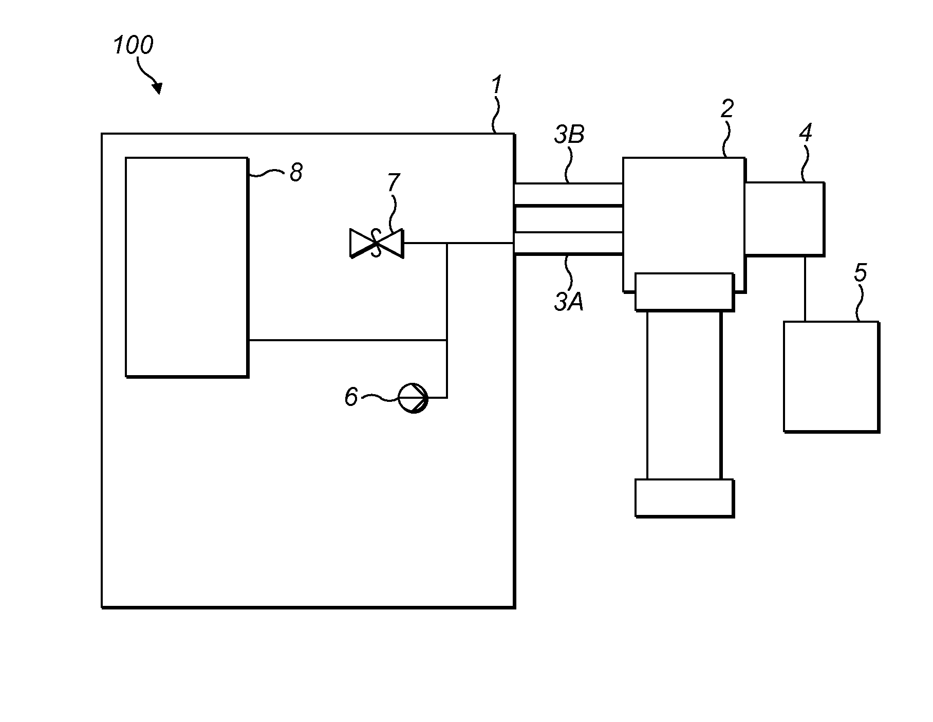
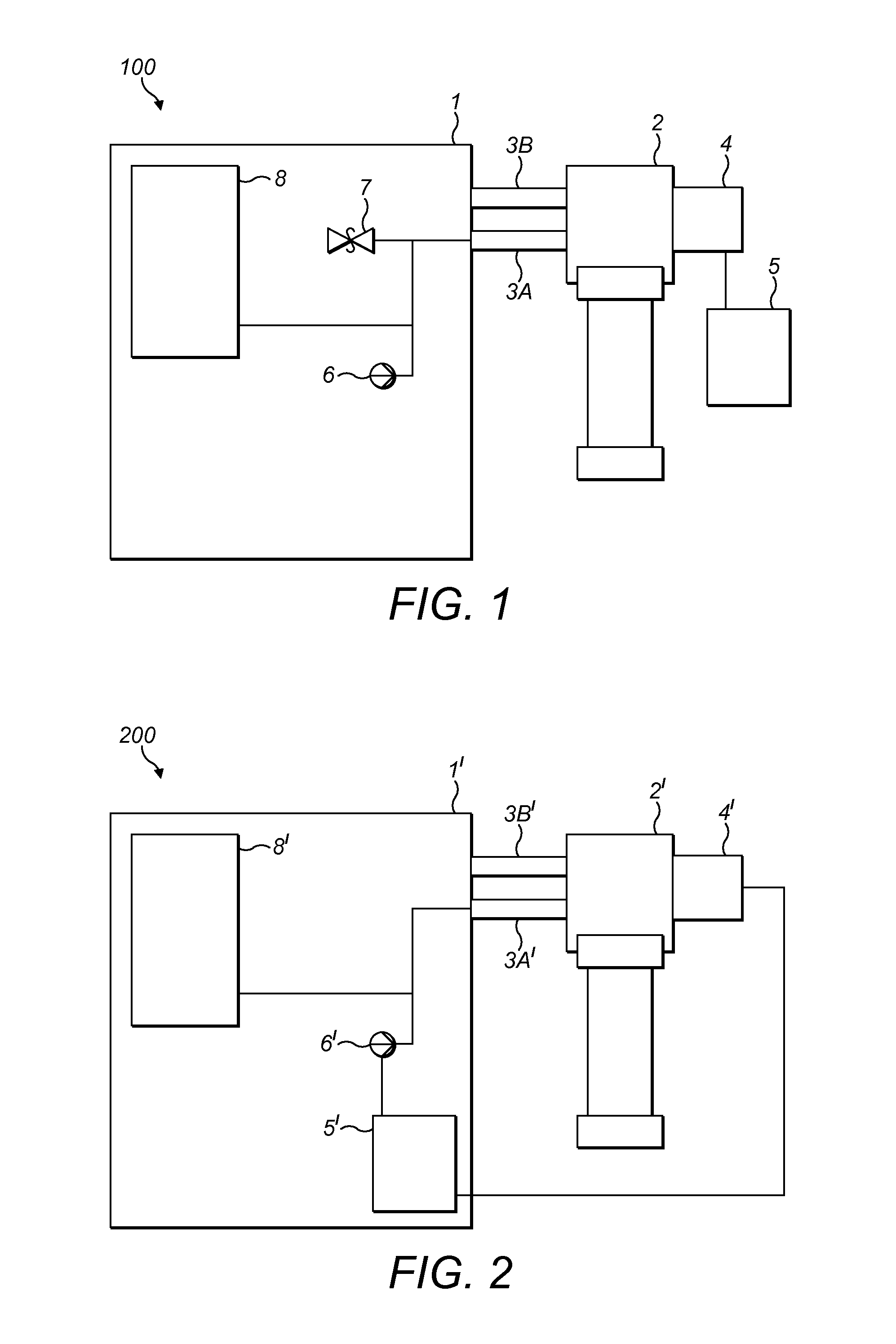
[0029]In order to provide a full understanding of the invention, we firstly describe a known closed cycle refrigerator (CCR) system in accordance with FIG. 1.

[0030]The system 100 comprises a scroll compressor 1 and a pulse tube refrigerator (PTR) 2. Two gas lines 3A and 3B connect the scroll compressor 1 to the pulse tube refrigerator 2. The gas lines 3A and 3B are essentially gas pipes which are capable of withstanding a high pressure. The gas line 3A is a supply line which contains a coolant gas at a high pressure when in use. The line 3B is a return line in the form of a low pressure line. A coupling element in the form of a rotary valve 4 is illustrated as an integral part of the PTR 2. The rotary valve 4 is driven by a motor controller 5 and the operational speed of the motor is fixed to ensure a constant rotational frequency of the rotary valve given by a Foptimum. This frequency is designed to be the optimum frequency for use of the PTR once at its “cold” or steady-state oper...


PUM


Abstract

Apparatus for controlling a cryogenic cooling system is described. A supply gas line (3A) and a return gas line (3B) are provided which are coupled to a compressor (1) and to a mechanical refrigerator (2) via a coupling element (4). The coupling element is in gaseous communication with the supply (2A) and return gas lines and supplies gas to the mechanical refrigerator (2). The pressure of the supplied gas is modulated by the coupling element in a cyclical manner. A pressure sensing apparatus (6) monitors the pressure in at least one of the supply and return gas lines. A control system (5) is used to modulate the frequency of the cyclical gas pressure supplied by the coupling element in accordance with the pressure monitored by the pressure sensing apparatus. An associated method of controlling such a system is also described.

Description

FIELD OF THE INVENTION[0001]The present invention relates to an apparatus and method for controlling a cryogenic cooling system, particularly one in which certain types of gas compressor are used to drive mechanical refrigerators.BACKGROUND TO THE INVENTION[0002]Low temperature properties such as superconductivity and superfluidity are now widely used in a range of different applications including Magnetic Resonance Imaging (MRI), superconducting magnets, sensors and in fundamental research. Historically, the evaporation of cryogenic liquids such as nitrogen or helium has been used as a cooling mechanism in order to reach the low temperatures required for such applications. Cryogenic liquids have associated disadvantages in that they are often “consumable” due to leaks within associated apparatus such as “in situ” liquefiers or storage vessels. Furthermore such apparatus for storing or otherwise handling cryogenic liquids is often bulky and requires special handling procedures.[0003...

Claims


Application Information

Patent Timeline
IPC IPC(8): F25B49/00
CPCF25B49/00F25B9/14F25B2309/006F25B2309/1427F25B2309/1428F25B2700/19F25B2600/25F25B49/02H01F6/04
Inventor GARSIDE, JOHNBUEHLER, MATTHIASTORTORELLA, DANIELSYUAN, XING
Owner OXFORD INSTR NANOTECH TOOLS
Why Eureka
Try Eureka