Display device

a display device and display technology, applied in the field of display devices, can solve the problems of difficulty in ensuring the contrast of the above-described display device, and achieve the effects of prolonging the moving time of the penetrant, and reducing the difficulty of above-described display devices

Inactive Publication Date: 2005-06-23
FUJIFILM HLDG CORP +1
View PDF6 Cites 5 Cited by
  • Summary
  • Abstract
  • Description
  • Claims
  • Application Information

AI Technical Summary

Benefits of technology

[0028] According to the present invention, the display device is further equipped with a transparent penetrant storage layer, interposed between the transparent porous layer and the colored layer, for storing the penetrant. When the penetrant penetrates into the transparent porous layer, the penetrant storage layer supplies the penetrant from the penetrant storage layer to the transparent porous layer. When the penetrant is discharged from the transparent porous layer, the penetrant storage layer stores the discharged penetrant. Therefore, the supply and discharge of the penetrant with respect to the transparent porous layer can be readily performed. In addition, according to the present invention, the penetrant-moving means is made up of electrodes, which are respectively disposed on the top and bottom surfaces of the transparent porous layer; and a potential difference application part for applying a potential difference between the electrodes disposed on the top and bottom surfaces of the transparent porous layer. This makes it possible to exert the Coulomb force on the penetrant more reliably.
[0029] According to the present invention, a pore diameter in the transparent porous layer is made greater the further it is away from the colored layer in the direction of the thickness of the two layers. For example, when the transparent porous layer is displayed by discharging the penetrant from the transparent porous layer, and when the colored porous layer is displayed by penetration of the penetrant into the transparent porous layer, a change in display can be made appropriate. Therefore, when a specified brightness is shifted to a brightness different from that brightness, the afterimage of the display can be optimized. Also, when the colored layer is a colored porous layer with pores into which a penetrant is penetrable, a region of the transparent porous layer in contact with the colored layer plays a role of preventing the moving time of the penetrant from being too short when the penetrant in the colored layer penetrates into the transparent porous layer during application of the Coulomb force, if a pore diameter in that contact region is made smallest and the thickness of a region whose pore diameter is smaller than that of the colored layer is made sufficiently thinner than that of the colored layer. In addition, when no Coulomb force is exerted, the penetrant in the transparent porous layer plays a role of resistance in penetrating into the colored layer and can prolong the moving time of the penetrant. Thus, display is able to have an afterimage (memory effect).
[0030] According to the present invention, a pore diameter in the transparent porous layer is between 0.1 μm and 10 μm. When the colored layer is the colored porous layer, a pore diameter in the colored porous layer is between 0.1 μm and 10 μm. Therefore, penetration and discharge of the penetrant with respect to the transparent porous layer and colored porous layer can be more easily performed.
[0031] According to the present invention, the penetrant-moving means is able to exert the Coulomb forces of different magnitudes on the penetrant in the thickness direction at different positions on a plane perpendicular to the thickness direction. This makes it possible to change brightness at different positions. For example, images can be displayed. In addition, the colored layer can be colored in different hues at different positions on a plane perpendicular to the thickness direction. This renders it possible to display color images.

Problems solved by technology

However, because there is no possibility that light incident on the surface, on which the top electrodes 83 are disposed and in which the grooves 81 are not formed, will be utilized for display, it is difficult for the above-described display device to have sufficient contrast.

Method used


Image

  • Display device
  • Display device
  • Display device

Examples


first embodiment

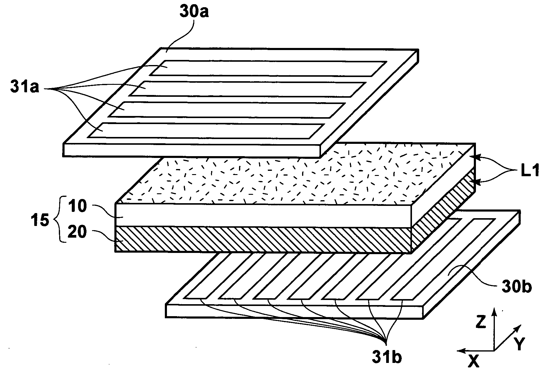
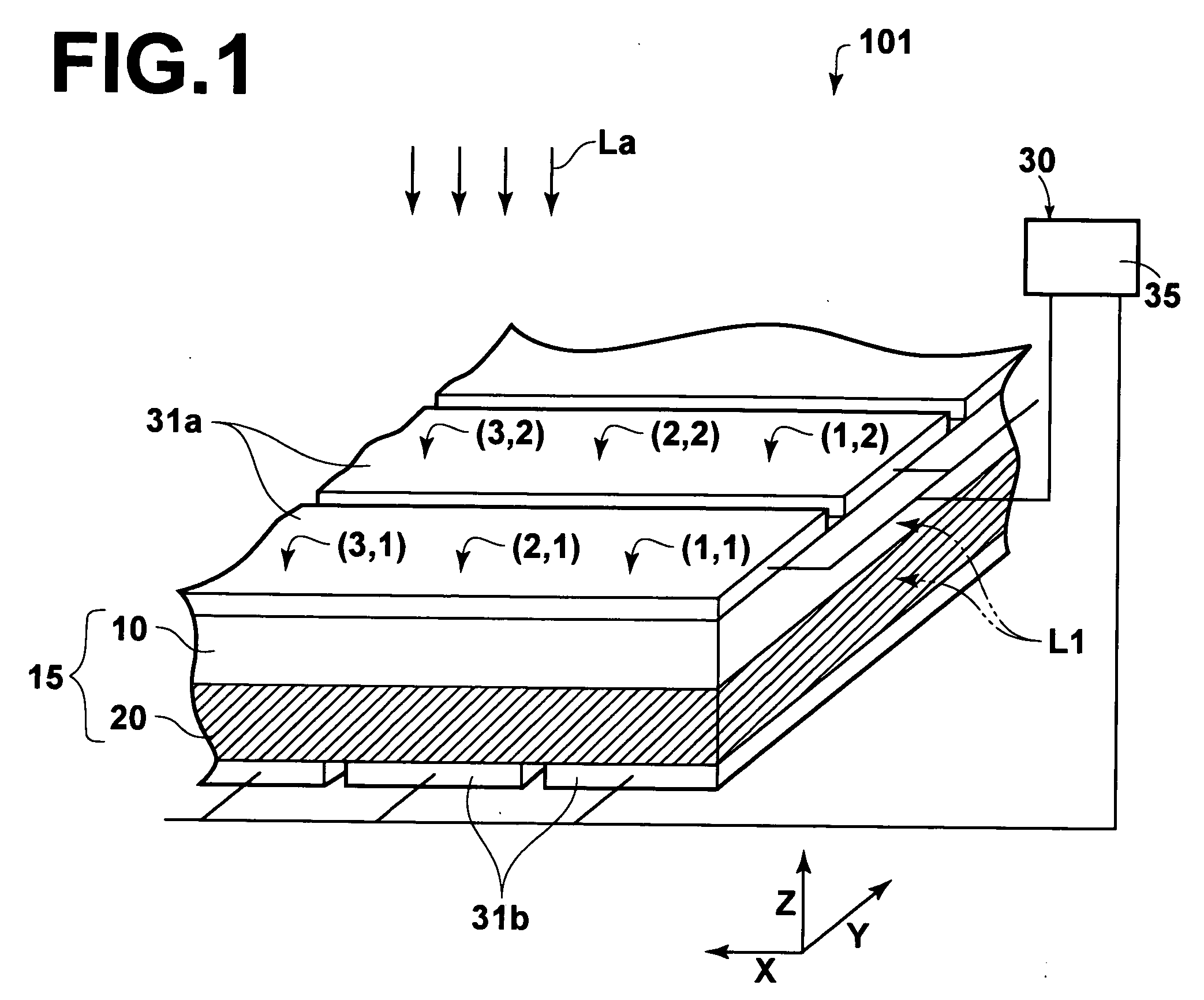
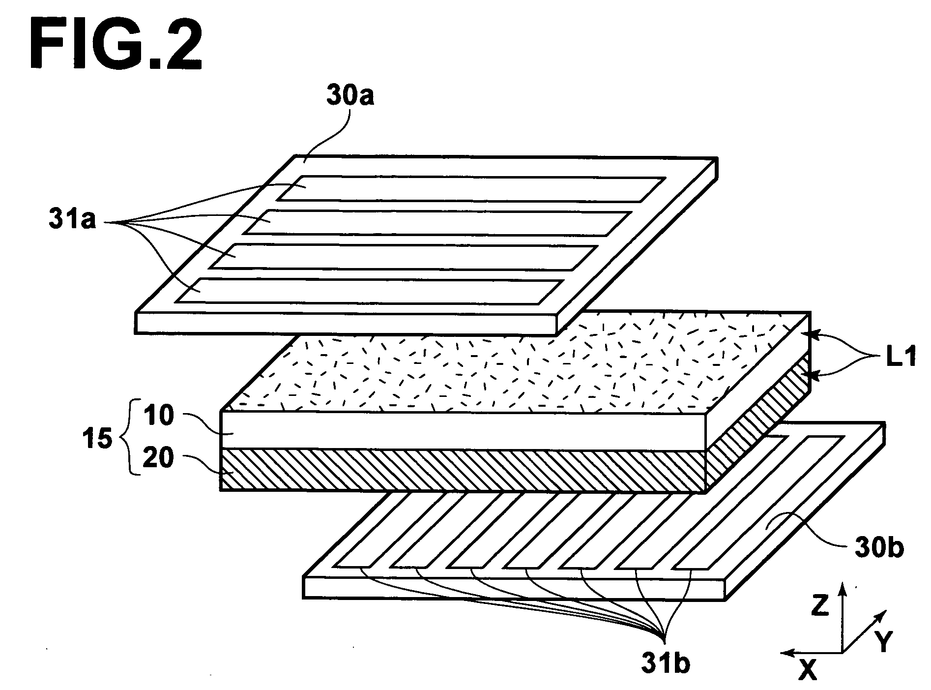
[0053] Referring to FIGS. 1 through 4, there is shown a display device 101 constructed in accordance with the present invention.

[0054] The display device 101 is formed from a transparent material, and includes a transparent porous layer 10 with pores into which a penetrant L1 is penetrable; a colored layer 20 stacked on one surface of the transparent porous layer 10; and penetrant-moving means 30 for exerting the Coulomb force on the penetrant L1 to perform penetration of the penetrant L1 into the transparent porous layer 10 or discharge of the penetrant L1 from the transparent porous layer 10.

[0055] In the display device 101, when the penetrant L1 penetrates into the transparent porous layer 10, the transparent porous layer 10 becomes transparent and therefore the colored porous layer 20 is displayed through the transparent porous layer 10. On the other hand, when the penetrant L1 is discharged from the transparent porous layer 10, the transparent porous layer 10 becomes opaque an...

second embodiment

[0101] Referring to FIG. 9, there is shown a display device 102 constructed in accordance with the present invention.

[0102] The display device 102 is formed from a transparent material, and includes a transparent porous layer 50 with pores into which a penetrant L1 is penetrable; a colored layer 60 stacked on one surface of the transparent porous layer 50; penetrant-moving means 70 for exerting the Coulomb force on the penetrant L1 to perform penetration of the penetrant L1 into the transparent porous layer 50 or discharge of the penetrant L1 from the transparent porous layer 50; and a penetrant storage layer 80 for storing the penetrant L1 between the transparent porous layer 50 and the colored layer 60.

[0103] In the display device 102, when the penetrant L1 penetrates into the transparent porous layer 50, the transparent porous layer 50 becomes transparent and therefore the colored porous layer 60 is displayed through the transparent porous layer 50. On the other hand, when the p...

third embodiment

[0116] Referring to FIGS. 10A through 10D, there is shown a display device 103 constructed in accordance with the present invention.

[0117] The display device 103 of the third embodiment is formed from a transparent material, and includes a transparent porous layer 110 with pores into which a penetrant L1 is penetrable; a colored porous layer 120 stacked on one surface of the transparent porous layer 110; and penetrant-moving means 30 for exerting the Coulomb force on the penetrant L1 to perform penetration of the penetrant L1 into the transparent porous layer 110 or discharge of the penetrant L1 from the transparent porous layer 110.

[0118] In the display device 103, when the penetrant L1 penetrates into the transparent porous layer 110, the transparent porous layer 110 becomes transparent and therefore the colored porous layer 120 is displayed through the transparent porous layer 110. On the other hand, when the penetrant L1 is discharged from the transparent porous layer 110, the ...


PUM

PropertyMeasurementUnit
pore diameteraaaaaaaaaa
transparentaaaaaaaaaa

Abstract

A display device is made up of a transparent porous layer, a colored layer, and a penetrant-moving part. The transparent porous layer is formed from a transparent material and has pores into which a penetrant is penetrable. The colored layer is stacked on one surface of the transparent porous layer. The penetrant-moving part is used for performing penetration of the penetrant into the transparent porous layer or discharge of the penetrant from the transparent porous layer. After the penetration of the penetrant into the transparent porous layer performed by the penetrant-moving part, the transparent porous layer becomes transparent and therefore the colored layer is displayed through the transparent porous layer. After the discharge of the penetrant from the transparent porous layer performed by the penetrant-moving part, the transparent porous layer becomes opaque and therefore the transparent porous layer is displayed.

Description

BACKGROUND OF THE INVENTION [0001] 1. Field of the Invention [0002] The present invention relates to a display device, and more particularly to a display device making use of the movement of a penetrant under the influence of an electric field. [0003] 2. Description of the Related Art [0004] There is known a display device that performs display by changing the reflection, refraction, and scattering of light incident on a porous body, utilizing the movement of a penetrant into the porous body across which a difference of potential is applied. For example, as shown in FIGS. 11A and 11B, such a display device is made up of a transparent porous panel 82 with a great number of grooves 81 formed in the screen; top electrodes 83a (which are also used as light-intercepting plates) disposed on the top surface of the porous panel 82; and transparent bottom electrodes 83b disposed on the bottom surface of the porous panel 82 (see Japanese Unexamined Patent Publication No. 56(1981)-88177). This...

Claims


Application Information

Patent Timeline
Patent Type & Authority Applications(United States)
IPC IPC(8): G02F1/17B32B3/26B32B5/18B41M5/00G02B26/02G09F9/30G09G5/00
CPCB32B5/18G09G2300/08G09G3/3433G02B26/004Y10T428/249953Y10T428/31725
Inventor SONODA, SHINICHIROFUJII, TAKAMICHI
Owner FUJIFILM HLDG CORP
Why Eureka
Try Eureka