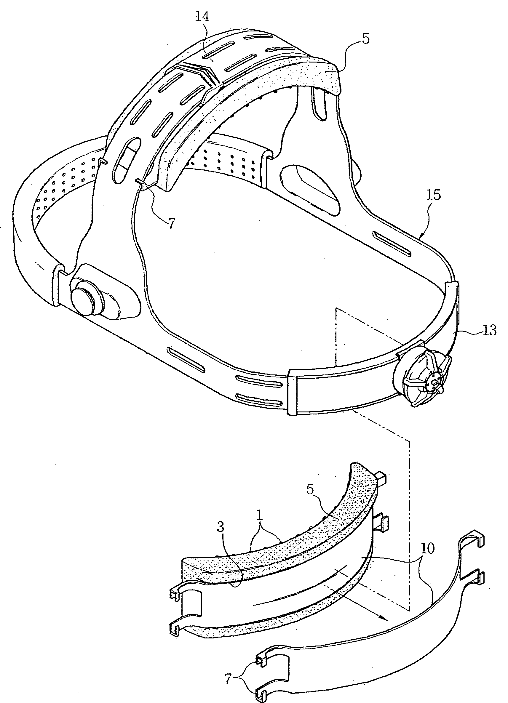
Cushion pad structure for headband
a technology of cushion pad and headband, which is applied in the direction of helmet covers, protective garments, hats, etc., can solve the problems of serious difficulties in work, disadvantageous biasing of safety hats, and difficulty in maintaining proper balance, so as to ensure stable and convenient wearing of protective equipment, and maintain the uniform balance of headbands
- Summary
- Abstract
- Description
- Claims
- Application Information
AI Technical Summary
Benefits of technology
Problems solved by technology
Method used
Image
Examples
first embodiment
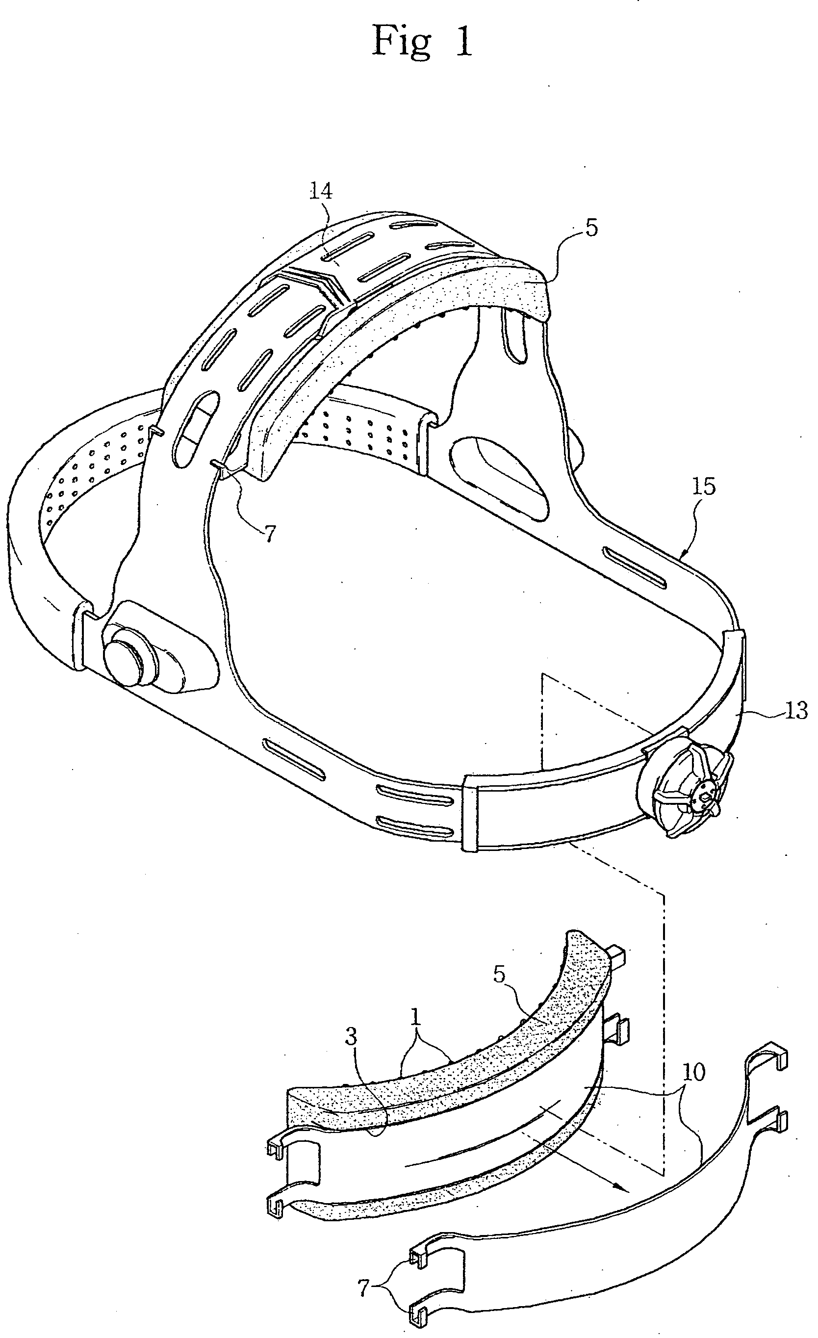
[0028]FIG. 1 is a perspective view illustrating the general configuration of a cushion pad structure in accordance with the present invention. The cushion pad structure comprises a cushion pad 5, and a fixing clip 10, which is integrally molded to the cushion pad 5, and is adapted to be coupled to an adjustable headband 15.
[0029] The cushion pad 5, molded from a soft material, has a plurality of slip-prevention pieces 1, having a constant thickness, formed at an inner peripheral surface thereof, and a groove 3 formed at an outer peripheral surface thereof. Herein, the inner peripheral surface of the cushion pad 5 means a surface coming into contact with the wearer's head, and the outer peripheral surface thereof means a surface to be coupled to the headband 15.
[0030] It should be noted that the slip-prevention pieces 1 are variable in shape without being limited to that shown in FIG. 1, and thus may be shaped into vertical or horizontal recesses, or corrugated or crucial portions. ...
second embodiment
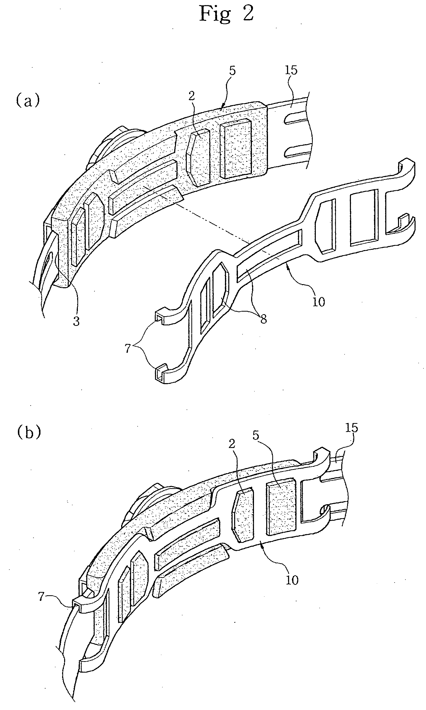
[0034]FIGS. 2a and 2b illustrate a cushion pad structure in accordance with the present invention. In the present embodiment, elements similar to those of the previous embodiment are denoted by the same reference numerals as them. A cushion pad 5 and a fixing clip 10 of the present embodiment are separately formed using an injection molding process, and then are coupled to each other.
[0035] Here, the fixing clip 10 is adapted to be coupled to an inner peripheral side of the cushion pad 5.
[0036] For this, the cushion pad 5 has a plurality of protrusions 2 formed at the inner peripheral surface thereof, and at an outer peripheral surface of the cushion pad 5 is defined a groove 3. The groove 3 of the cushion pad 5 is configured to receive the clamp member 13 therein.
[0037] The fixing clip 10 is formed with a plurality of through holes 8 having the same shape as that of the protrusions 2 formed at the cushion pad 5, and U-shaped fastening pieces 7 at both lateral ends thereof.
[0038]...
third embodiment
[0039]FIG. 3 illustrates a cushion pad structure in accordance with the present invention wherein elements similar to those of the previous embodiments are denoted by the same reference numerals as them.
[0040] In the present embodiment, a fixing clip 10 is positioned to be coupled to an outer peripheral surface of a cushion pad 5. The cushion pad 5 has a plurality of slip-prevention pieces 1 formed at an inner peripheral surface thereof, and a plurality of protruding pieces 3 formed inside a groove 3 defined at the outer peripheral surface thereof.
[0041] The fixing clip 10, to be integrally coupled to the cushion pad 5, has a plurality of through holes 8 having the same shape as that of the protruding pieces 3a formed at the cushion pad 5, and U-shaped fastening pieces 7 formed at upper and lower edges of both lateral ends thereof.
[0042] The coupling of the cushion pad 5 and fixing clip 10 is performed in the same manner as that of the above second embodiment.
[0043] In order to b...
PUM
 Abstract
Description
Claims
Application Information
 - R&D
- Intellectual Property
- Life Sciences
- Materials
- Tech Scout
- Unparalleled Data Quality
- Higher Quality Content
- 60% Fewer Hallucinations
Browse by: Latest US Patents, China's latest patents, Technical Efficacy Thesaurus, Application Domain, Technology Topic, Popular Technical Reports.
© 2025 PatSnap. All rights reserved.Legal|Privacy policy|Modern Slavery Act Transparency Statement|Sitemap|About US| Contact US: help@patsnap.com


