Cushion pad structure for headband

a technology of cushion pad and headband, which is applied in the direction of helmet covers, protective garments, hats, etc., can solve the problems of serious difficulties in work, disadvantageous biasing of safety hats, and difficulty in maintaining proper balance, so as to ensure stable and convenient wearing of protective equipment, and maintain the uniform balance of headbands

Active Publication Date: 2005-11-22
OTOS TECH
View PDF9 Cites 65 Cited by
  • Summary
  • Abstract
  • Description
  • Claims
  • Application Information

AI Technical Summary

Benefits of technology

[0010]Therefore, the present invention has been made in view of the above problems, and it is an object of the present invention to provide a soft pad structure for a headband, which is added to a rear portion of the adjustable headband so as to maintain the uniform balance of the headband, thereby securing stable and convenient wearing of protective equipment, such as a safety hat, on a wearer's head.

Problems solved by technology

Such a configuration, wherein only to the front portion of the clamp member is added the sponge sheet, makes it difficult to maintain the proper balance of the clamp member, and causes friction between the wearer's hair and the clamp member, thereby causing disadvantageous biasing of a safety hat.
This results in serious difficulties in work.
Moreover, since the clamp member and support member of the headband are configured so that they come into close contact with the wearer's head so as not to allow inflow of outside air, in case of using the safety hat, in hot weather during summer, it is inconvenient in use since a wearer has to frequently take off it in order to remove sweat.

Method used


Image

  • Cushion pad structure for headband
  • Cushion pad structure for headband
  • Cushion pad structure for headband

Examples


first embodiment

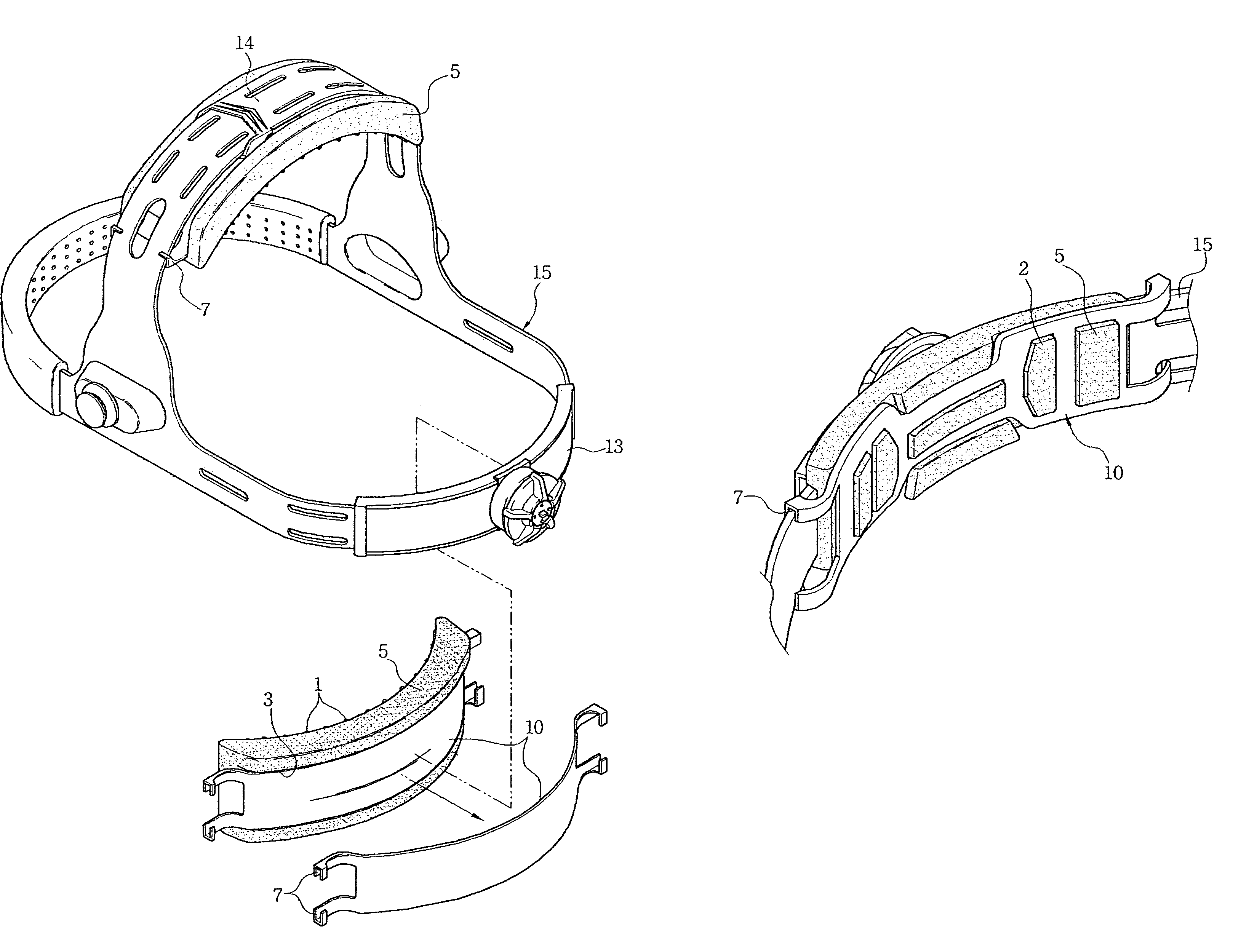
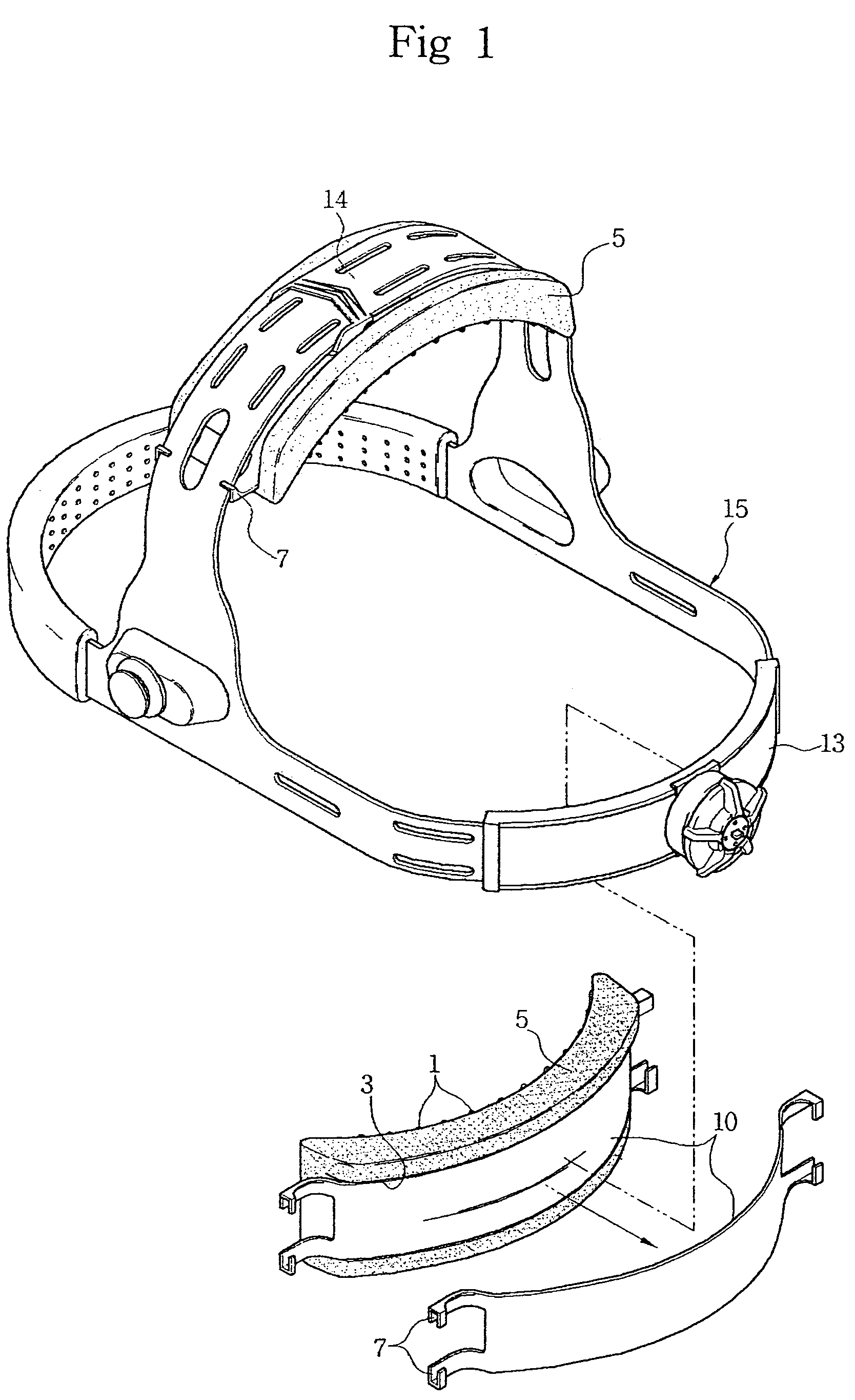
[0028]FIG. 1 is a perspective view illustrating the general configuration of a cushion pad structure in accordance with the present invention. The cushion pad structure comprises a cushion pad 5, and a fixing clip 10, which is integrally molded to the cushion pad 5, and is adapted to be coupled to an adjustable headband 15.

[0029]The cushion pad 5, molded from a soft material, has a plurality of slip-prevention pieces 1, having a constant thickness, formed at an inner peripheral surface thereof, and a groove 3 formed at an outer peripheral surface thereof. Herein, the inner peripheral surface of the cushion pad 5 means a surface coming into contact with the wearer's head, and the outer peripheral surface thereof means a surface to be coupled to the headband 15.

[0030]It should be noted that the slip-prevention pieces 1 are variable in shape without being limited to that shown in FIG. 1, and thus may be shaped into vertical or horizontal recesses, or corrugated or crucial portions.

[003...

second embodiment

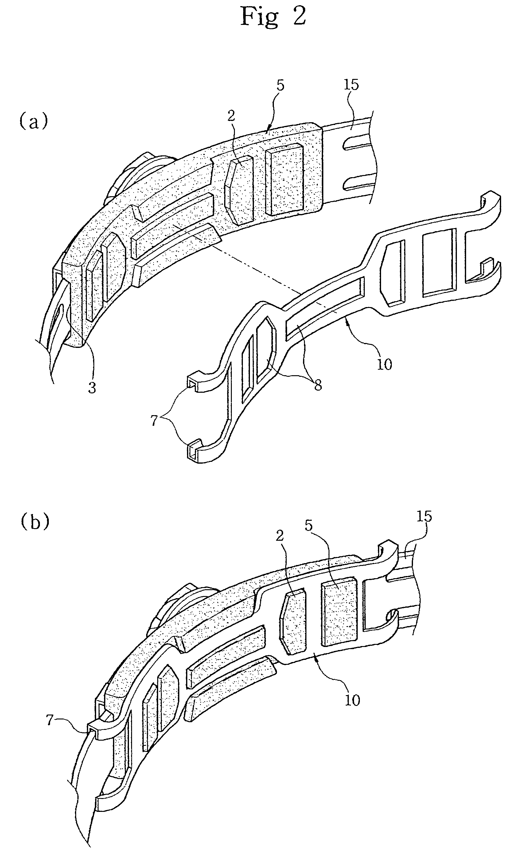
[0034]FIGS. 2a and 2b illustrate a cushion pad structure in accordance with the present invention. In the present embodiment, elements similar to those of the previous embodiment are denoted by the same reference numerals as them. A cushion pad 5 and a fixing clip 10 of the present embodiment are separately formed using an injection molding process, and then are coupled to each other.

[0035]Here, the fixing clip 10 is adapted to be coupled to an inner peripheral side of the cushion pad 5.

[0036]For this, the cushion pad 5 has a plurality of protrusions 2 formed at the inner peripheral surface thereof, and at an outer peripheral surface of the cushion pad 5 is defined a groove 3. The groove 3 of the cushion pad 5 is configured to receive the clamp member 13 therein.

[0037]The fixing clip 10 is formed with a plurality of through holes 8 having the same shape as that of the protrusions 2 formed at the cushion pad 5, and U-shaped fastening pieces 7 at both lateral ends thereof.

[0038]With s...

third embodiment

[0039]FIG. 3 illustrates a cushion pad structure in accordance with the present invention wherein elements similar to those of the previous embodiments are denoted by the same reference numerals as them.

[0040]In the present embodiment, a fixing clip 10 is positioned to be coupled to an outer peripheral surface of a cushion pad 5. The cushion pad 5 has a plurality of slip-prevention pieces 1 formed at an inner peripheral surface thereof, and a plurality of protruding pieces 3 formed inside a groove 3 defined at the outer peripheral surface thereof.

[0041]The fixing clip 10, to be integrally coupled to the cushion pad 5, has a plurality of through holes 8 having the same shape as that of the protruding pieces 3a formed at the cushion pad 5, and U-shaped fastening pieces 7 formed at upper and lower edges of both lateral ends thereof.

[0042]The coupling of the cushion pad 5 and fixing clip 10 is performed in the same manner as that of the above second embodiment.

[0043]In order to be fitte...


PUM


Abstract

Disclosed herein is a cushion pad structure, which is coupled to a headband as an integral component of safety hats, protective masks, and the like, so as to maintain the uniform balance of the headband, thereby securing stable wearing of the above protective equipment on a wearer's head, and preventing biasing thereof. The cushion pad structure comprises a cushion pad which has a plurality of slip-prevention pieces formed at an inner peripheral surface thereof, and a groove defined at an outer peripheral surface thereof, and a fixing clip which is configured to be engaged in the groove of the cushion pad, and has upper and lower U-shaped fastening pieces formed at both lateral ends thereof. The fixing clip is formed, using an injection molding process, such that it is integral with the cushion pad.

Description

BACKGROUND OF THE INVENTION[0001]1. Field of the Invention[0002]The present invention relates to a cushion pad structure for a headband, and more particularly to a cushion pad structure, which is coupled to a headband as an integral component of safety hats, protective masks, and the like, so as to maintain uniform balance of the headband, thereby securing stable wearing of the above protective equipment on a wearer's head, and preventing biasing thereof.[0003]2. Description of the Related Art[0004]To the inside of protective equipment, such as a safety hat or welding mask, is integrally fixed a headband for securing stable wearing of the protective equipment on a wearer's head.[0005]Such a headband comprises a clamp member configured to surround the circumference of the wearer's head, and a support member to be located on the vertex of the wearer's head. The clamp member and support member are integrally coupled to each other, and are freely adjustable in their size, especially, di...

Claims


Application Information

Patent Timeline
Patent Type & Authority Patents(United States)
IPC IPC(8): A42B3/00A42B3/14
CPCA42B3/14Y10S2/11
Inventor HUH, MOON YOUNG
Owner OTOS TECH
Why Eureka
Try Eureka