Externally activated seal system for wellhead

Active Publication Date: 2005-06-30
PLEXUS HOLDINGS PLC
View PDF9 Cites 19 Cited by
  • Summary
  • Abstract
  • Description
  • Claims
  • Application Information

AI Technical Summary

Benefits of technology

[0034] Internal tubing hanger lockdown can be accomplished without a dedicated handling tool and without potential control line damage Imp

Problems solved by technology

There are however applications where a fixed position casing hanger is unsatisfactory, because the hang-off point of one casing on another may require to be adjusted.
Wellheads of this type require higher-risk operations, as they require lifting the BOP to install casing slips and annulus seals.
The seals installed on

Method used


Image

  • Externally activated seal system for wellhead
  • Externally activated seal system for wellhead
  • Externally activated seal system for wellhead

Examples


Embodiment Construction

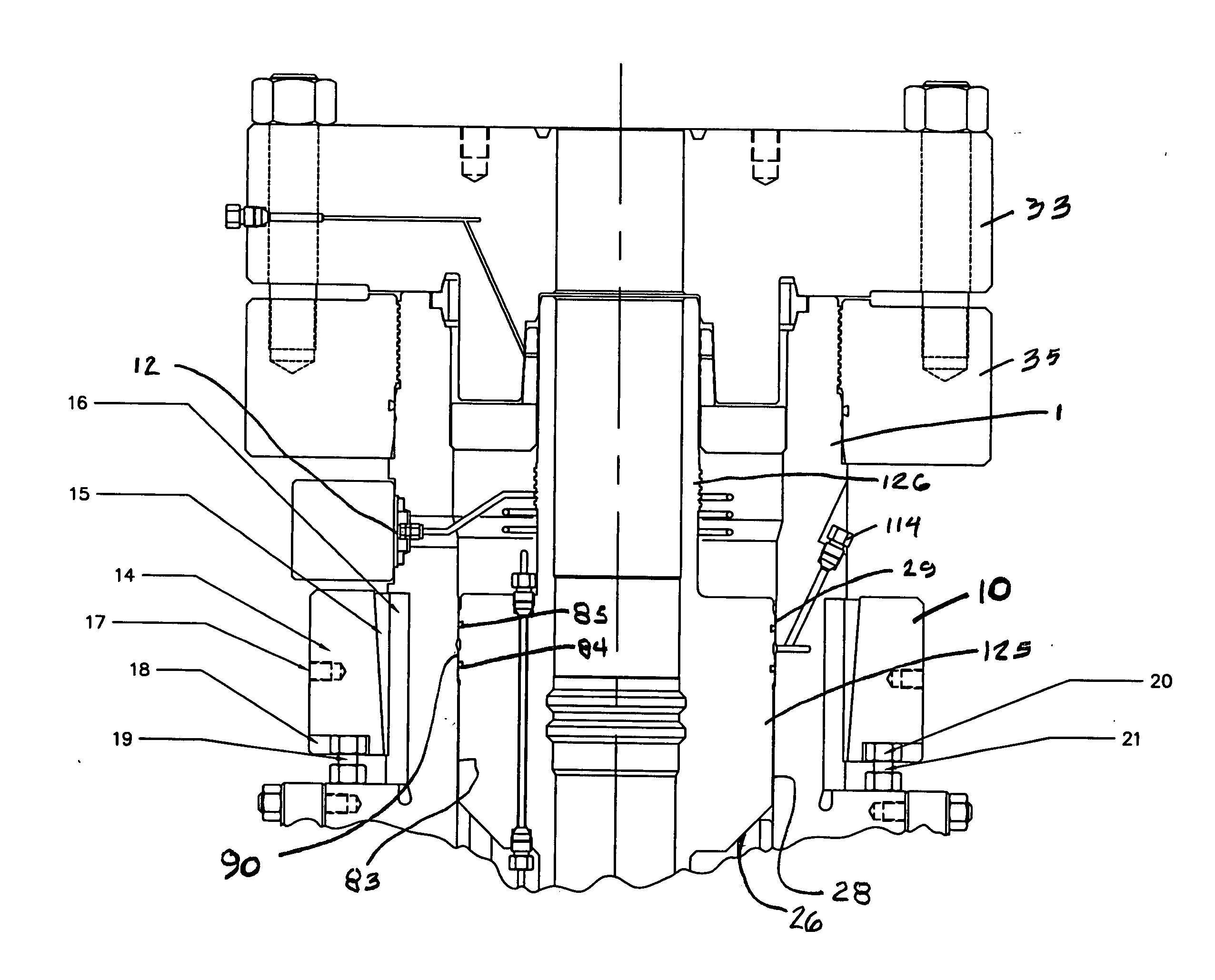
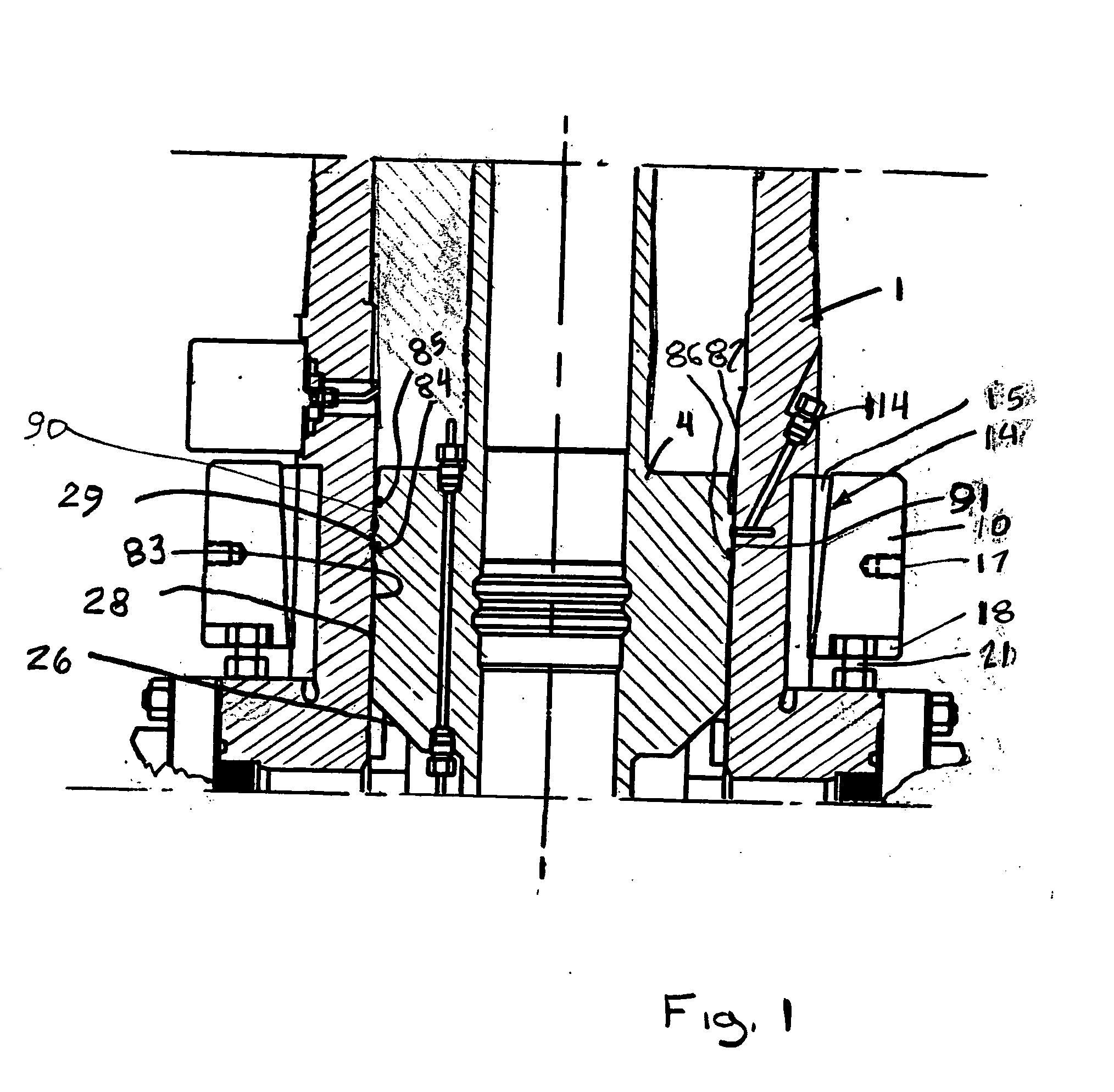
[0041] A simplified, diagrammatic view of the seal system to the subject invention is shown in FIG. 1. In its simplest form, the invention provides the apparatus and method for accomplishing a circumferential seal between two substantially concentric members by externally activating the seal once the two members are in position.

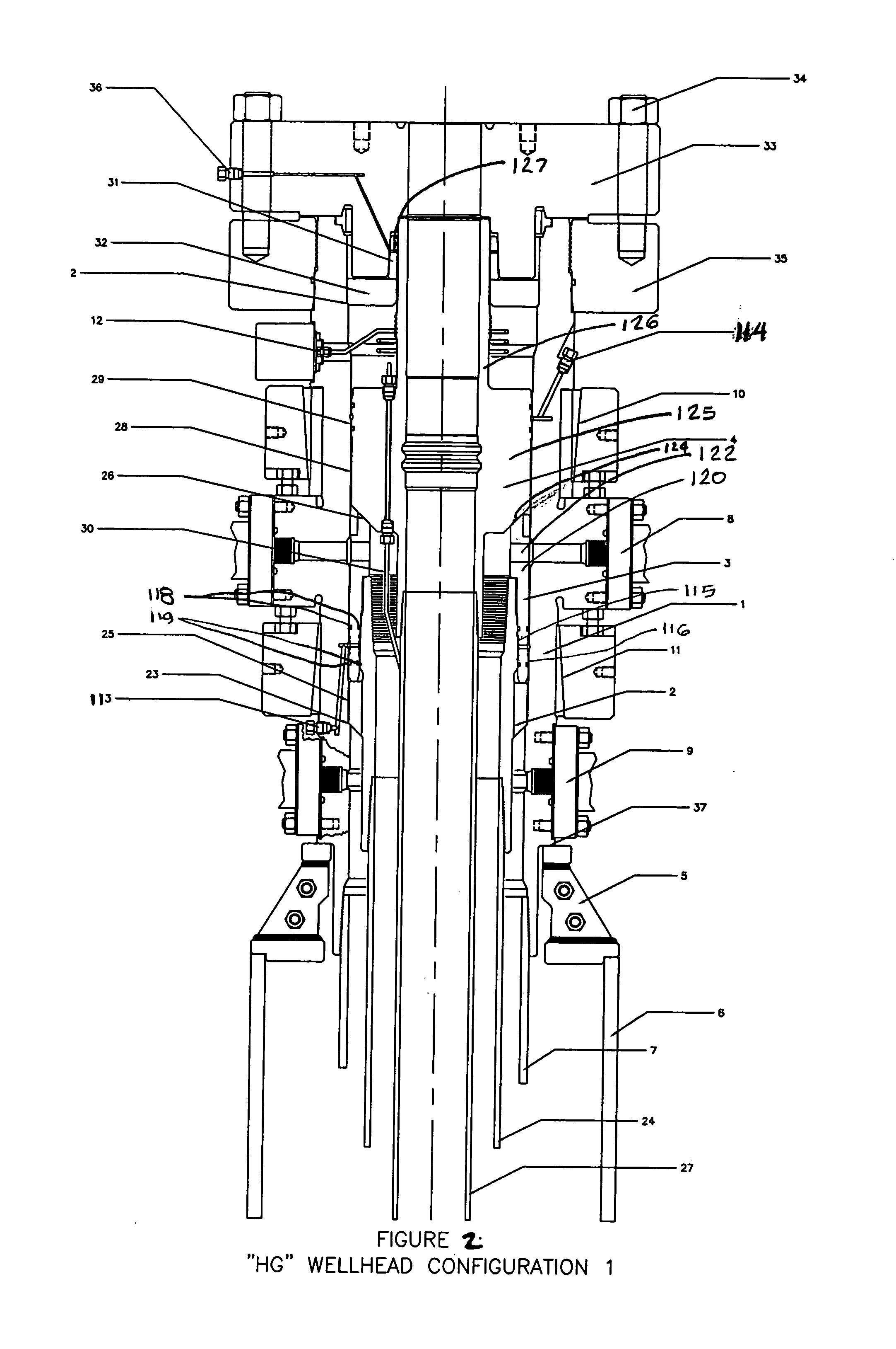
[0042] With specific reference to FIG. 1, a wellhead 1 includes having an external sealing apparatus 10 for clamping a tubular casing 4 of a first diameter within a tubular casing (here the wellhead 1) of larger internal diameter. The outer tubular member has an inner circumferential wall with a sealing zone 83. The inner tubular member is adapted to be positioned substantially concentrically within the outer tubular member having an outer circumferential wall with a sealing zone 28. The circumferential compression system 10 is mounted outwardly of the outer tubing member and operable to be activated for compressing the outer tubular member into contact with...


PUM


Abstract

A method and apparatus for a seal assembly for a unitized wellhead system for land or platform applications utilizes a friction grip technology to create maintainable metal-to-metal seals with finely-controlled contact stresses, lock-down casing and tubing hangers, support test loads to minimize the size of landing shoulders required, and to rotationally lock casing hangers to provide simplified running procedures. The system can be used in combination with a friction grip clamping assembly to greatly streamline the wellhead design.

Description

BACKGROUND OF THE INVENTION [0001] 1. Field of the Invention [0002] The invention is related to concentric casings and strings in wellheads wherein it is necessary to effect a seal between concentric members of the wellhead and is specifically directed to a seal system wherein the sealing members are activated via an external, non-invasive seal energizing system. [0003] 2. Discussion of the Prior Art [0004] In oil and gas wells, it is conventional to pass a number of concentric tubes or casings down the well. An outermost casing is fixed in the ground, and the inner casings are each supported from the next outer casing by casing hangers which take the form of inter-engaging internal shoulders on the outer casing and external shoulders on the inner casing. [0005] Typically, such casing hangers are fixed in position on each casing. There are however applications where a fixed position casing hanger is unsatisfactory, because the hang-off point of one casing on another may require to b...

Claims


Application Information

Patent Timeline
IPC IPC(8): E21B33/04
CPCE21B33/0422
Inventor VAN BILDERBEEK, BERNARD HERMAN
Owner PLEXUS HOLDINGS PLC
Why Eureka
Try Eureka