Flow restriction device
- Summary
- Abstract
- Description
- Claims
- Application Information
AI Technical Summary
Benefits of technology
Problems solved by technology
Method used
Image
Examples
Embodiment Construction
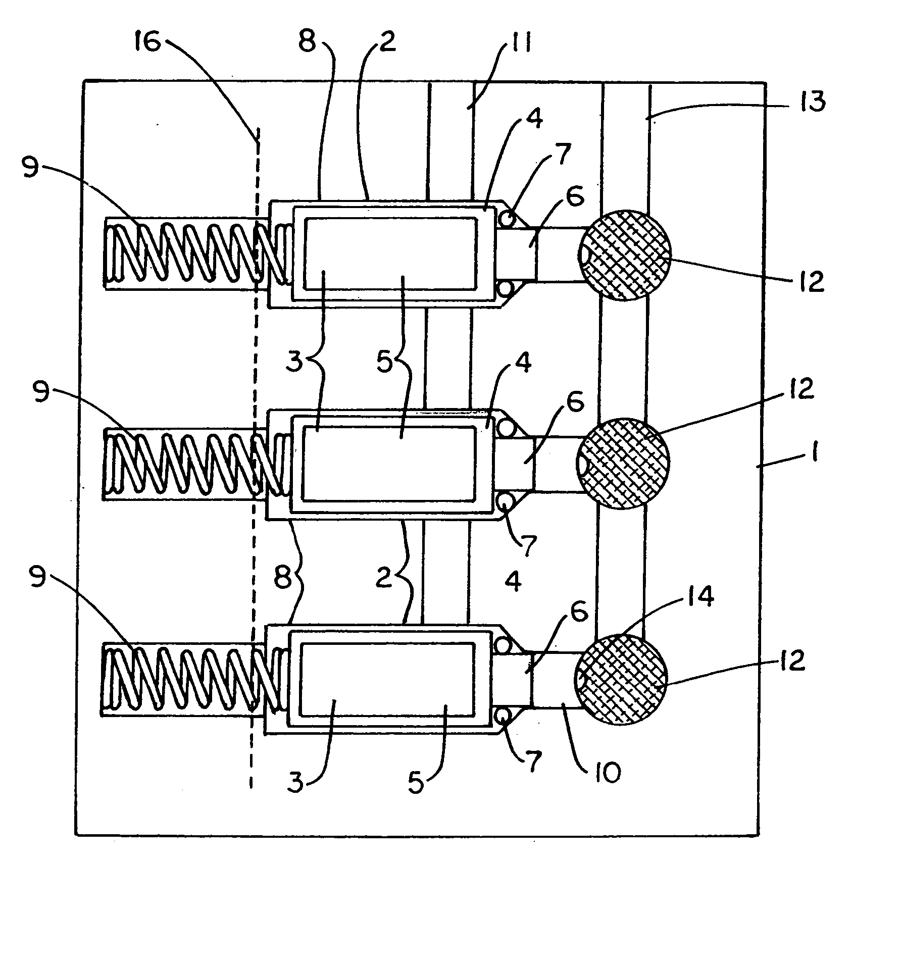
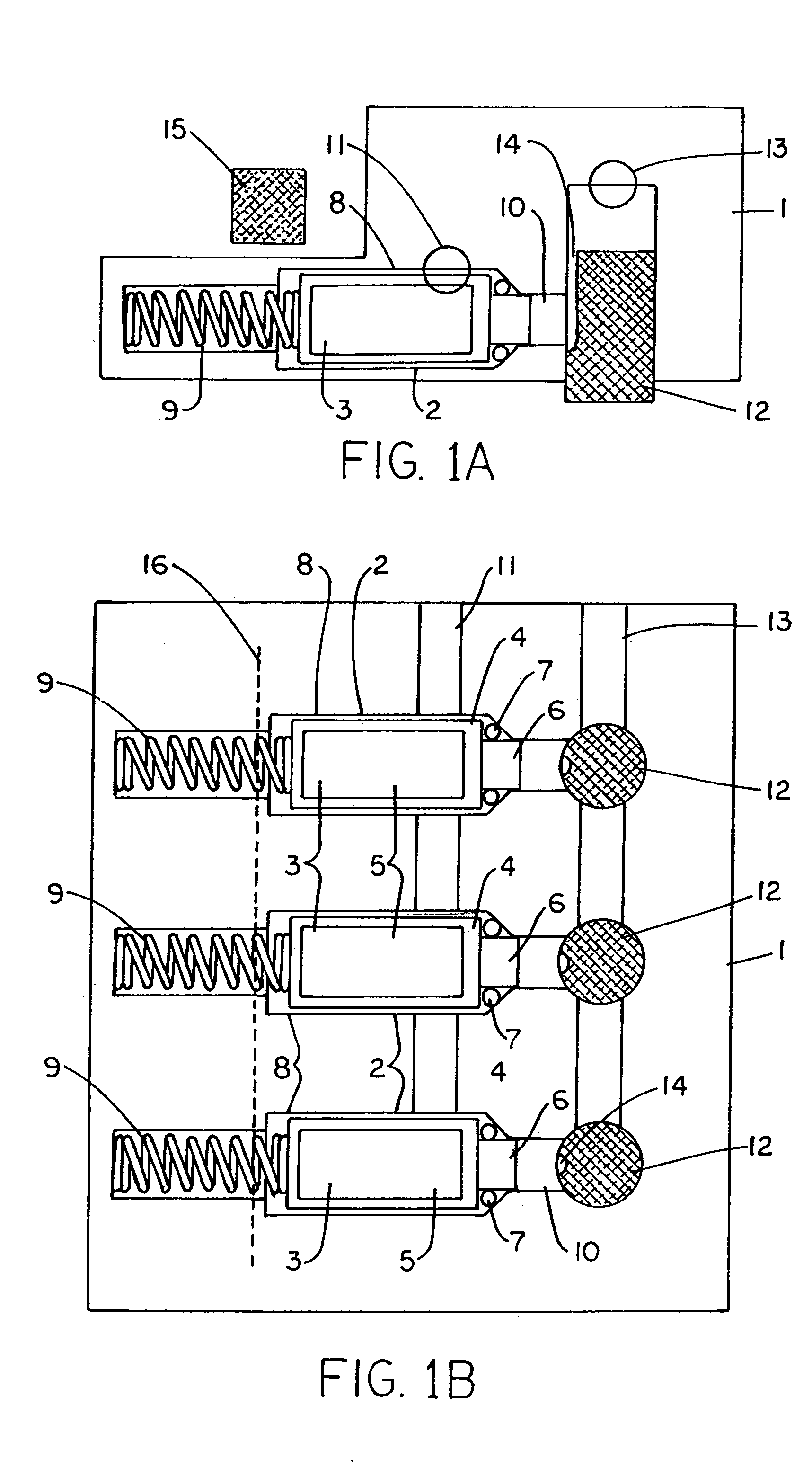
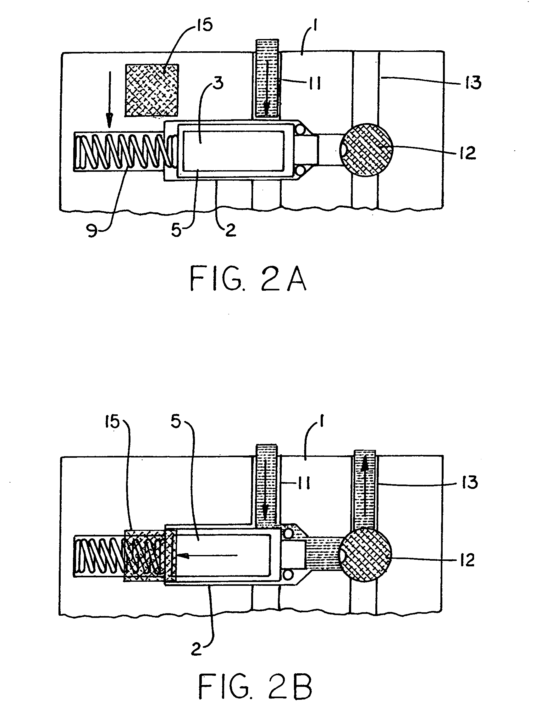
[0016] The flow restriction device embodying the invention shown in the figures has a body 1 formed of moulded plastics components and having within it interconnecting cavities for receiving other components and providing liquid flow paths. Located within cavities 8 of the body are three magnetically operated valves 2, each having a valve member 3 in the form of a moulded plastics body 4 containing a body of magnetisable material 5, such as soft iron and having a projection 6 at one end surrounded by an O-ring seal 7. The valve member 3 is slidable within the cavity 8 and biased by a spring 9 into the closed position of the valve in which the O-ring 7 abuts a tapering shoulder of the cavity 8 and in which the extremity of the projection 6 is received in a passage 10 which is an outlet from the valve cavity 8.
[0017] The cavities 8 of the three valves 2 are connected to a common inlet 11 of the flow-restriction device. They are also connected, via the passages 10 and flow restrictors...
PUM
 Abstract
Description
Claims
Application Information
 - R&D
- Intellectual Property
- Life Sciences
- Materials
- Tech Scout
- Unparalleled Data Quality
- Higher Quality Content
- 60% Fewer Hallucinations
Browse by: Latest US Patents, China's latest patents, Technical Efficacy Thesaurus, Application Domain, Technology Topic, Popular Technical Reports.
© 2025 PatSnap. All rights reserved.Legal|Privacy policy|Modern Slavery Act Transparency Statement|Sitemap|About US| Contact US: help@patsnap.com


