

In-plane switching liquid crystal display comprising compensation film for angular field of view using +A-plate and +C-plate
a liquid crystal display and compensation film technology, applied in non-linear optics, instruments, optics, etc., to achieve the effect of superior contrast characteristic and low color shi
- Summary
- Abstract
- Description
- Claims
- Application Information
AI Technical Summary
Benefits of technology
Problems solved by technology
Method used
Image

Examples
embodiment 1
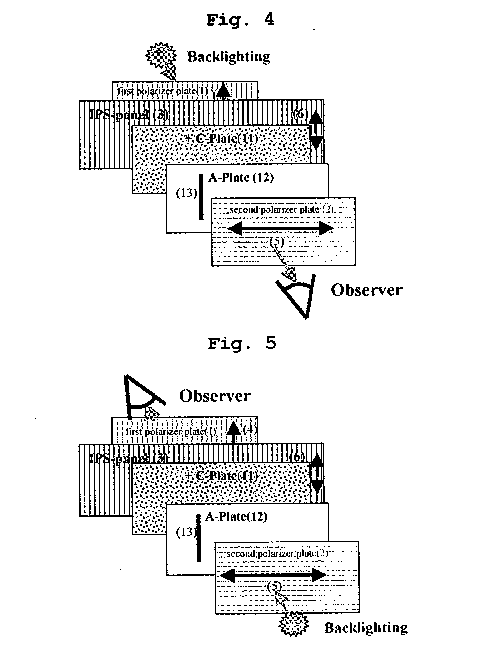
[0117] The IPS-LCD shown in FIG. 4 includes an IPS liquid crystal cell filled with liquid crystal having a cell gap of 2.9 μm, a pretilt angle of 3°, dielectric anisotropy of Δε=+7, and a birefringence of Δ n=0.1. The +C-plate 11 is fabricated by using an UV curable and homeotropically aligned liquid crystal film and has a thickness retardation value Rth=174 nm at a wavelength of 550 nm. The A-plate 12 is fabricated by using a stretched polycarbonate film and has an in-plane retardation value Rin=53 nm. The internal protective film for the first polarizer plate 1 is made from an isotropic COP film, and the internal protective film for the second polarizer plate 2 is made from a PNB (polynobonene) film having a thickness retardation value Rth=−130 nm. When a white light is used, the contrast characteristic of the IPS-LCD at an inclination angle of 0° to 80° in all azimuthal angles is illustrated in FIG. 10.
[0118] Referring to FIG. 10, a center of a circle corresponds to an inclinati...
embodiment 2
[0120] The IPS-LCD shown in FIG. 5 includes an IPS liquid crystal cell filled with liquid crystal having a cell gap of 2.9 μm, a pretilt angle of 3°, dielectric anisotropy of Δε=+7, and a birefringence of Δ n=0.1. The +C-plate 11 is fabricated by using an UV curable and homeotropically aligned liquid crystal film and has a thickness retardation value Rth=70 nm at a wavelength of 550 nm. The A-plate 12 is fabricated by using a stretched polycarbonate film and has an in-plane retardation value Rin=110. The internal protective film for the first and second polarizer plates 1 and 2 is made from a 40 μm TAC film having a thickness retardation value Rth=−32 nm.
[0121] When a white light is used, the contrast characteristic of the IPS-LCD at an inclination angle of 0° to 80° in all azimuthal angles is illustrated in FIG. 11. Referring to FIG. 11, the IPS-LCD represents the superior contrast characteristic above 50:1 at an inclination angle of 80°.
embodiment 3
[0122] The IPS-LCD shown in FIG. 6 includes an IPS liquid crystal cell filled with liquid crystal having a cell gap of 2.9 μm, a pretilt angle of 3°, dielectric anisotropy of Δε=+7, and a birefringence of Δ n=0.1. The +C-plate 11 is fabricated by using an UV curable and homeotropically aligned liquid crystal film and has a thickness retardation value Rth=91 nm at a wavelength of 550 nm. The A-plate 12 is fabricated by using a stretched polycarbonate film and has an in-plane retardation value Rin=148. The internal protective film for the first and second polarizer plates 1 and 2 is made from an isotropic COP film. When a white light is used, the contrast characteristic of the IPS-LCD at an inclination angle of 0° to 80° in all azimuthal angles is illustrated in FIG. 12. Referring to FIG. 12, the IPS-LCD represents the superior contrast characteristic above 200:1 at an inclination angle of 80°.
PUM
 Abstract
Description
Claims
Application Information