Heat sink retention device

a technology of retention device and heat sink, which is applied in the direction of lighting, heating apparatus, and semiconductor/solid-state device details, etc., can solve the problems of unsteady mounting, difficult to reliably retain such an increscent large heat sink to the socket, and increase the mass of the heat sink, etc., to achieve convenient fabrication and operation.

Inactive Publication Date: 2005-06-30
HON HAI PRECISION IND CO LTD
View PDF4 Cites 25 Cited by
  • Summary
  • Abstract
  • Description
  • Claims
  • Application Information

AI Technical Summary

Benefits of technology

[0010] It is an object of the present invention to overcome the above-mentioned problem so as to provide a heat sink retention device easy to fabricate and operate.

Problems solved by technology

This results in an increased mass for the heat sink.
Generally, the size of a socket is generally changeless, reliably retaining such an increscent large heat sink to the socket is difficult because of imparity of size between the heat sink and the socket.
An apparent disadvantage of this method is unsteadiness of mounting.
The hooks are prone to jump out of the mounting holes due to mechanical shock or vibration during the operation of the processor, which results in the heat sink's departing from the processor and consequently the temperature of the processor's dramatically increasing.
Another deflect also should not be ignored that the printed circuit board is prone to be damaged because of direct contacting force exerted by the spring clip, especially during mounting and removing the heat sink.
However, it is required to affix extra structure to the printed circuit board.
On the other hand, a retention force between the heat sink and the printed circuit board could indirectly result in deformation of the printed circuit board as the increase of retention force for securing the heat sink along with the increase of volume of the heat sink.
However, as any one skilled in the art has known, mounting a heat sink using screws is inconvenient, and making screw eyes in the pillars is not an efficient fabrication.
A more dramatic disadvantage is that it is difficult to ensure the joining forces between the screws and the pillars in different place balance.
Unbalanced joining forces will result in deformation of the printed circuit board and bad contact between the heat sink and the processor.

Method used


Image

  • Heat sink retention device
  • Heat sink retention device
  • Heat sink retention device

Examples


Embodiment Construction

[0019] In the following detailed description of the invention, reference is made to the accompanying drawings which form a part thereof, and in which is shown, by way of illustration, specific embodiments in which the invention may practiced. The embodiment is described in sufficient detail to enable those skilled in the art to practice the invention. Other embodiments may be utilized and structural, logical changes may be made without departing from the spirit of the present invention.

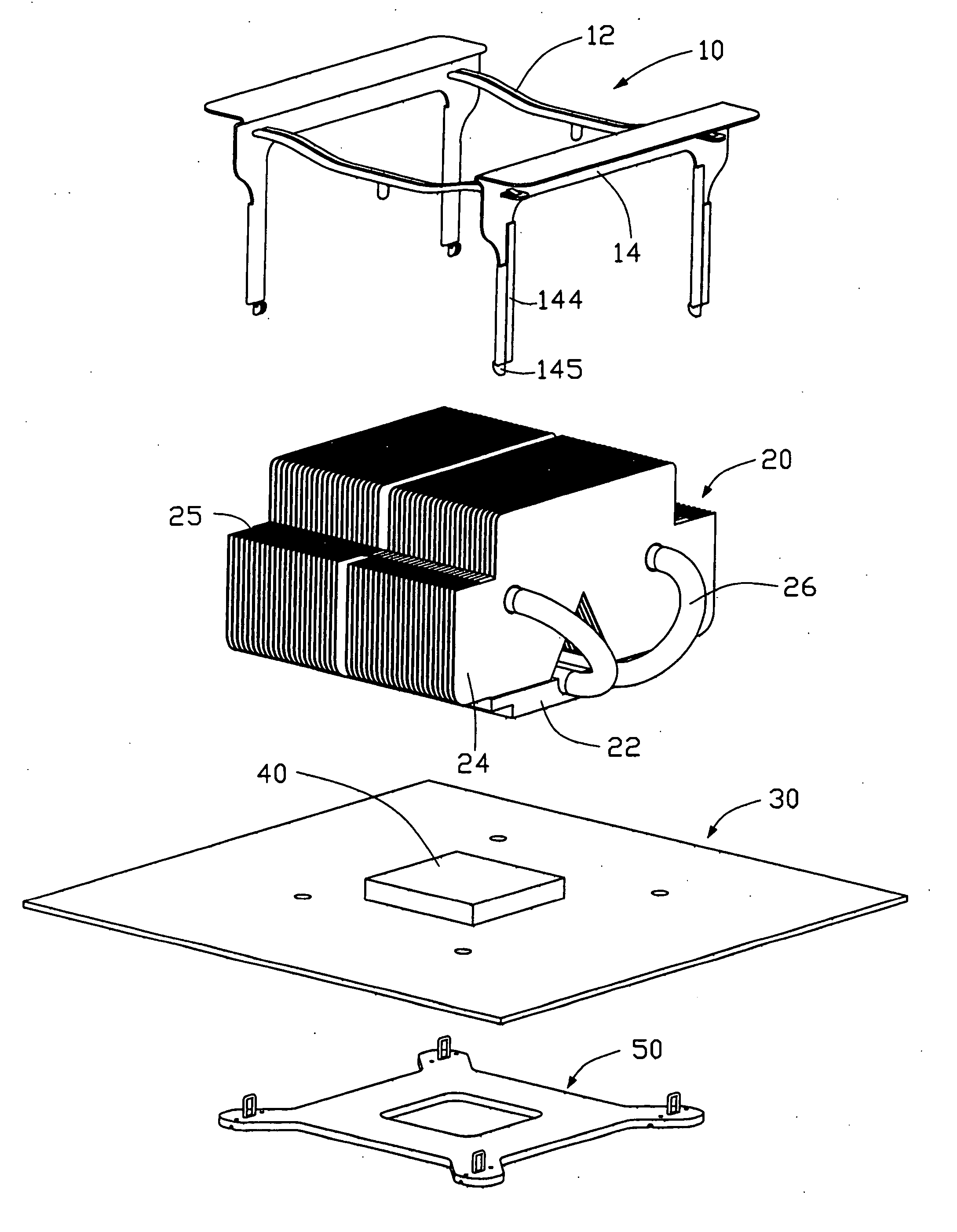
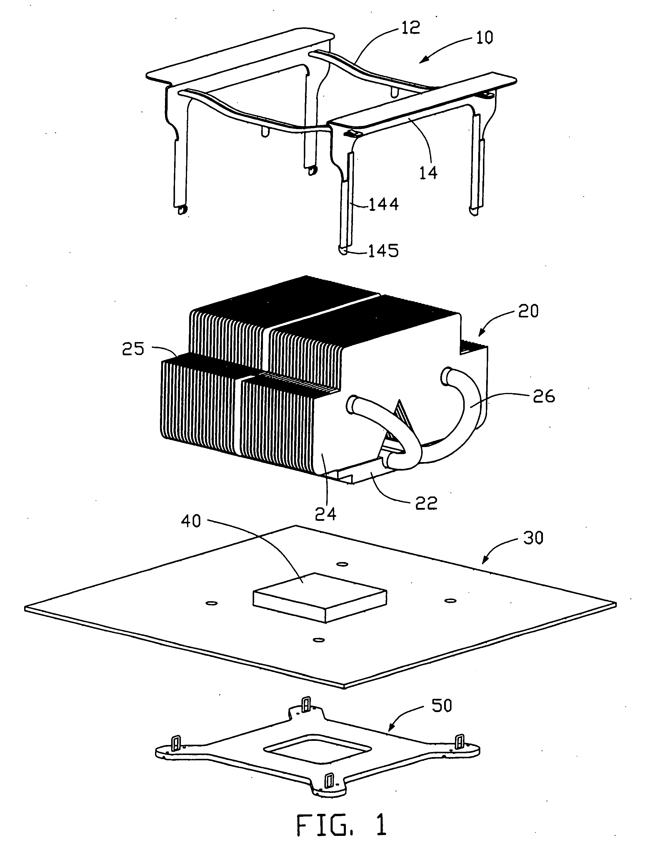
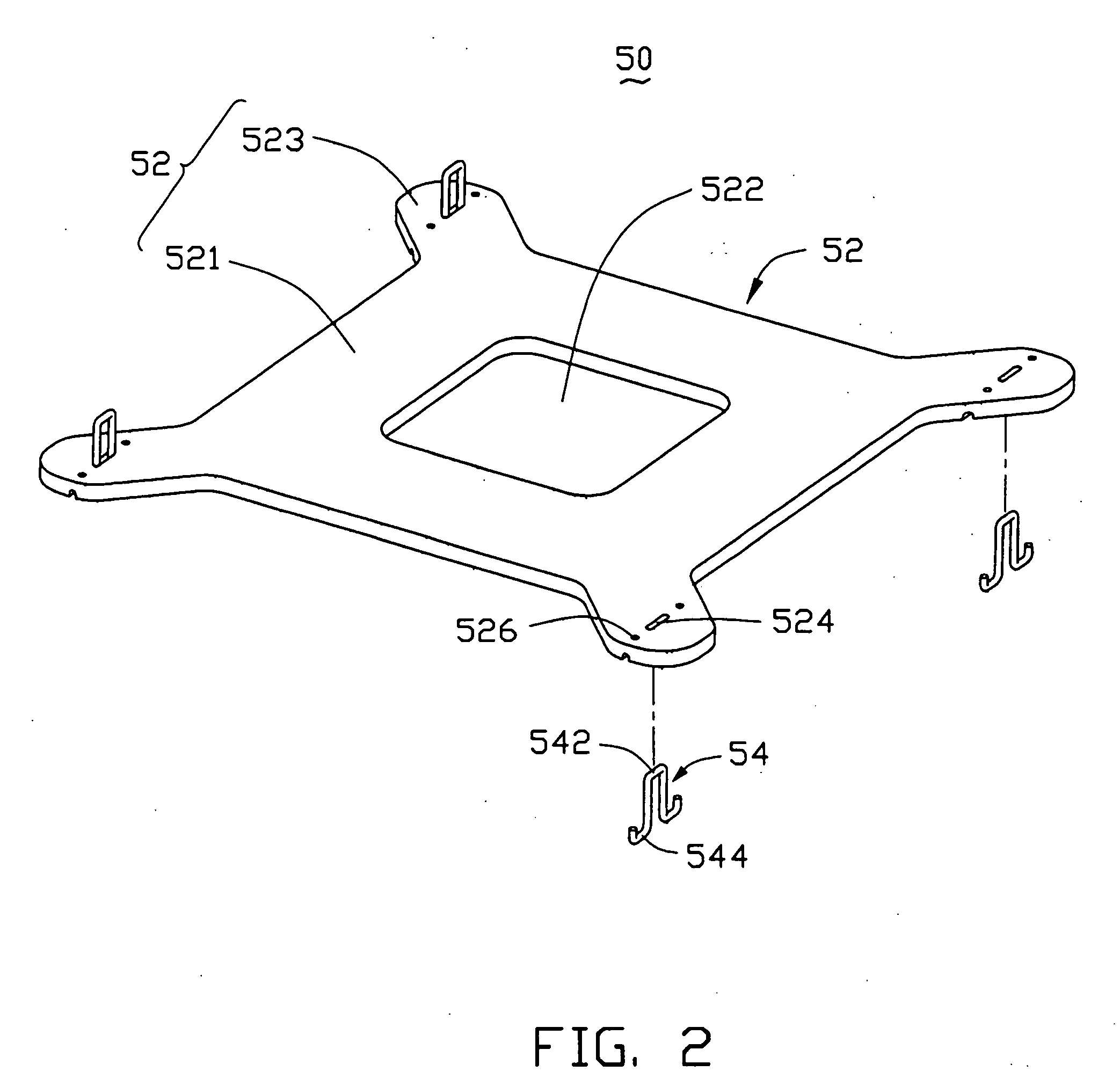
[0020] Referring to FIG. 1, a heat sink retention device, accompanying with a heat sink 20 and a printed circuit board 30 on which a processor 40 is mounted, in accordance with the present invention is illustrated. The retention device comprises a clip 10 for securing the heat sink 20 and a back plate 50 engaged with the clip 10.

[0021] The heat sink 20 comprises a metal base 22 for contacting with and absorbing heat from the processor 40, a plurality of fins 24 disposed on the base 22 and several he...


PUM


Abstract

The retention device comprises a clip and a back plate engaging the clip, the clip comprises pressing members for press the heat sink onto the processor and at least a pair of hooks, the back plate is placed below a printed circuit board on which the processor is mounted, and comprises a body and at least a pair of retaining rings mounted thereof. The retaining rings travel through mounting holes in the printed circuit board and beyond the top surface thereof for catching the hooks of the clip.

Description

BACKGROUND OF THE INVENTION [0001] 1. Field of the Invention [0002] The present invention relates generally to a retention device, and particularly to a heat sink retention device including a back plate. [0003] 2. Related Art [0004] Historically, when microprocessors were first commercialized, each microprocessor held less than one million transistors, and operated at speeds below 20 MHz. Typically, the microprocessors were either directly mounted to a printed circuit board by soldering or mounted to the printed circuit board via sockets. [0005] With the continuing and rapid development of integrated circuits technology, the number of transistors contained in each microprocessor, as well as the processor operating speed, has increased dramatically. Correspondingly, the amount of heat that needs to be dissipated has increased. As a result, today's microprocessors used in computer systems almost employ heat sinks with fans to ensure that microprocessors run within their normal operati...

Claims


Application Information

Patent Timeline
Patent Type & Authority Applications(United States)
IPC IPC(8): G06F1/16H01L23/40H01L23/427H05K7/20
CPCH01L23/4093H01L23/427H01L2924/0002H01L2924/00
Inventor LEE, HSIEH-KUNLI, DONG-YUNSHI, HONG-BO
Owner HON HAI PRECISION IND CO LTD
Why Eureka
Try Eureka