Wireless multi-hop system with macroscopic multiplexing

a wireless multi-hop and multi-hop technology, applied in the field of high data rate wireless transmission systems and methods, can solve the problem that the capacity of the first radio interface may not be sufficient to reliably carry all communication between the rs and bs, and achieve the effect of reliably carrying all communication and sufficient communication capacity of the wireless link

Active Publication Date: 2005-06-30
INTELLECTUAL VENTURES I LLC
View PDF13 Cites 100 Cited by
  • Summary
  • Abstract
  • Description
  • Claims
  • Application Information

AI Technical Summary

Benefits of technology

[0009] The present invention is directed to a method, device, and system in which radio links between relays and users are optimized separately from the links between relays and base stations and in which multiple simultaneous data streams between relays and base stations are created. The system includes transceivers of at least three kinds with at least two kinds of radio interfaces. The first kind of transceiver, a base station (BS), is connected to the core network with a link of wire line quality. A wire line quality link may be realized using a wireless communication link, whenever the communication capacity of the wireless link is sufficient to reliably carry all communication between the BS and the core network. The capacity of the first radio interface may not be sufficient to reliably carry all communication between the RS and BS. The second kind of transceiver, a relay station (RS), is connected to the BS with a first radio interface, and to the third kind, the user equipment (UE), with a second radio interface. The first and second radio interfaces can operate, at least in part, using the same frequency bandwidth. The UE can also connect directly to the BS using the second radio interface if the channel to / from the BS is better that the channel to / from any RS.

Problems solved by technology

The capacity of the first radio interface may not be sufficient to reliably carry all communication between the RS and BS.

Method used


Image

  • Wireless multi-hop system with macroscopic multiplexing
  • Wireless multi-hop system with macroscopic multiplexing
  • Wireless multi-hop system with macroscopic multiplexing

Examples


Embodiment Construction

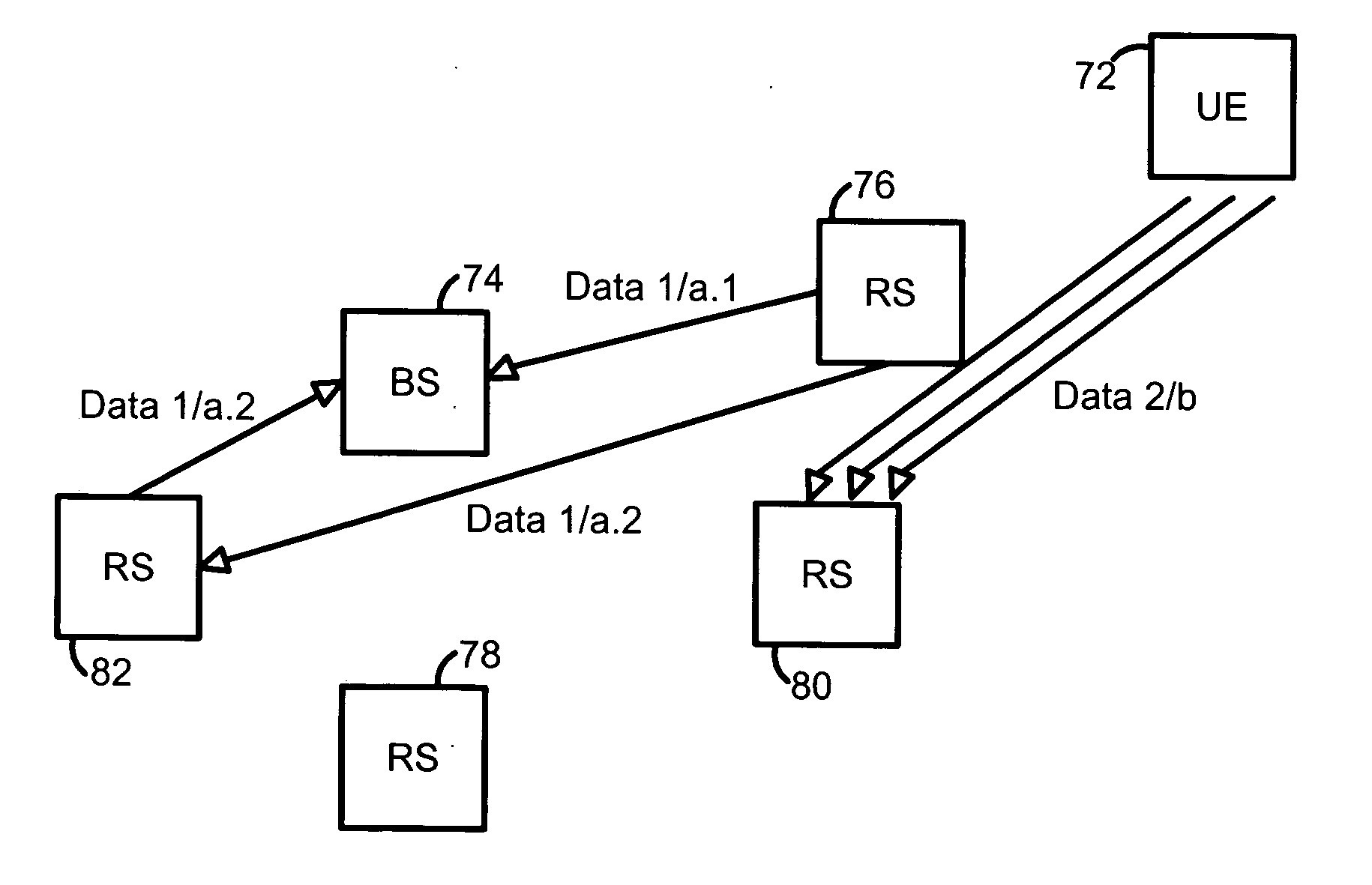
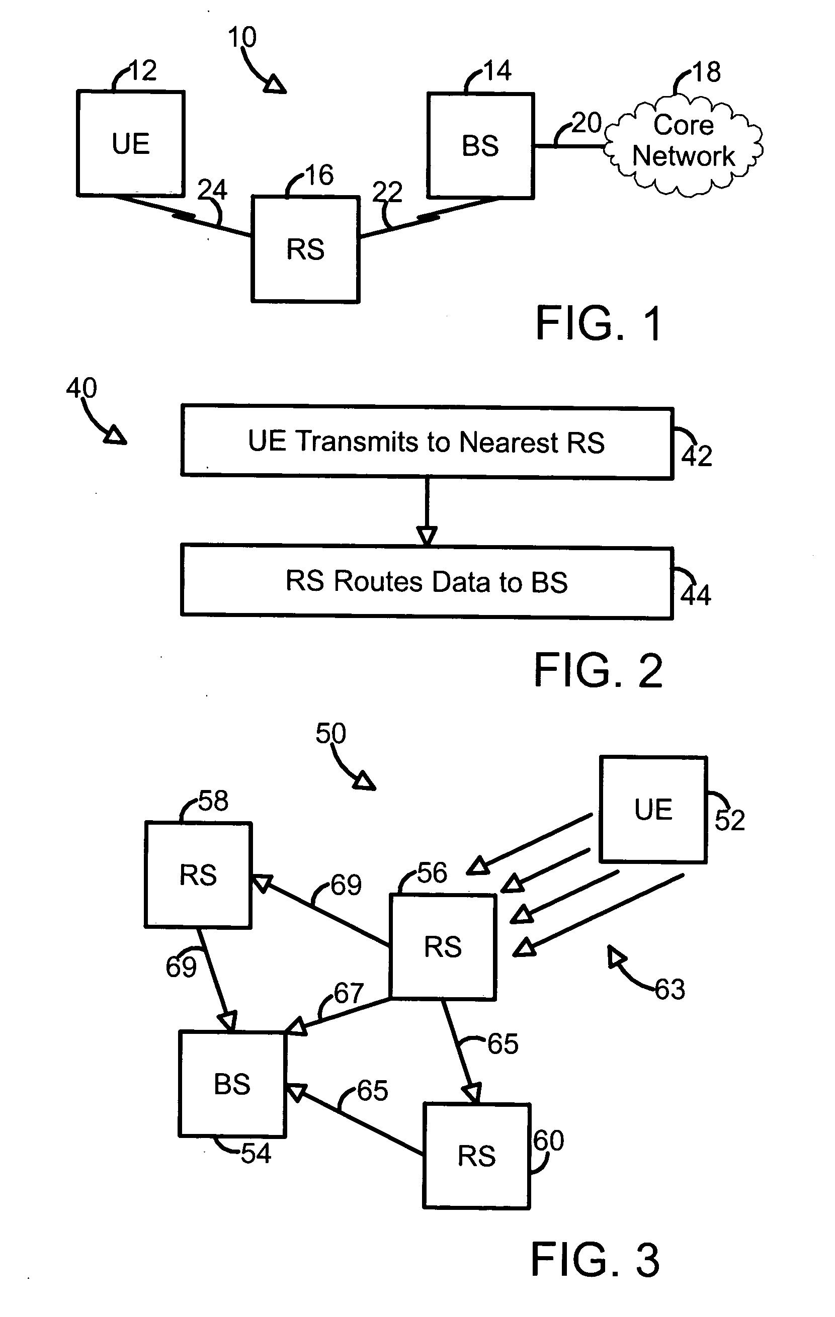
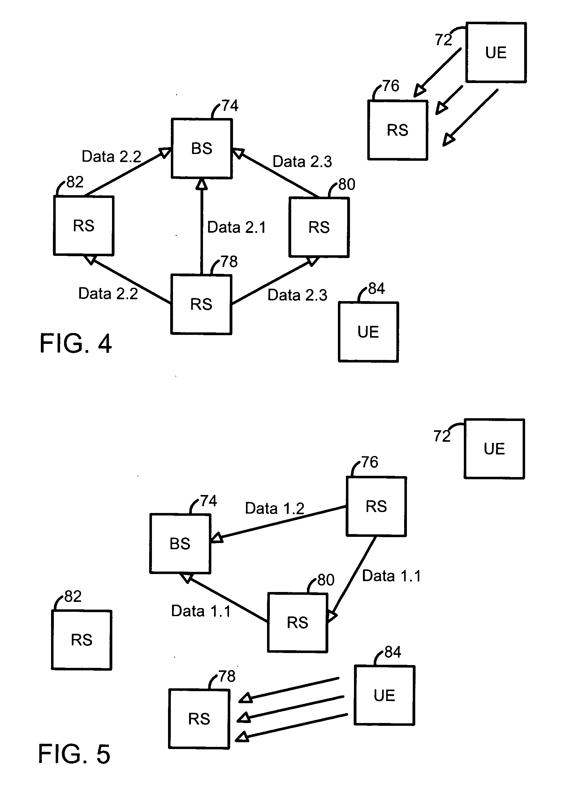
[0022]FIG. 1 illustrates a communication system 10 having a user equipment (UE) 12, a base station (BS) 14, a relay station (RS) 16, and a core network 18. The base station 14 is connected to the core network 18 with a wire line 20 having wire line quality. The relay station 16 is connected to the base station 14 by a radio interface 22 and the relay station 16 is connected to the UE 12 by a radio interface 24. In some embodiments, the radio interface 22 and the radio interface 24 operate, at least in part, using the same frequency bandwidth. In at least some radio interfaces, a macroscopic multiplexing is utilized, where the relay station 16 is connected to the base station 14 both directly and via another relay station. In at least some other radio interfaces, a multiple input, multiple output (MIMO) transmission is used.

[0023]FIG. 2 illustrates a flow diagram 40 of exemplary operations in a wireless multi-hop system with macroscopic multiplexing. Additional, fewer, or different ...


PUM


Abstract

A method, device, and system in which radio links between relays and users are optimized separately from the links between relays and base stations and in which multiple simultaneous data streams between relays and base stations are created. The system includes transceivers of at least three kinds with two kinds of radio interfaces. The first kind of transceiver, a base station (BS), is connected to the core network with a link of wire line quality. The second kind, a relay station (RS), is connected to the BS with a first radio interface, and to the third kind, the user equipment (UE), with a second radio interface. The first and second radio interfaces can operate, at least in part, using the same frequency bandwidth. The UE can also connect directly to the BS using the second radio interface if the BS is closer than any RS.

Description

FIELD OF THE INVENTION [0001] The present invention relates generally to high data rate wireless transmission systems and methods. More particularly, the present invention relates to a wireless multi-hop system with macroscopic multiplexing. BACKGROUND OF THE INVENTION [0002] As is known, engineers and scientists strive to develop wireless communication systems that achieve high data rates at relatively low costs. High data rates are often attainable by design but cannot be implemented because costs are prohibitive. [0003] In fourth-generation wireless systems (known as “4G” systems), capacities of 1 Gbps for a local area and 10 Mbps for wide area coverage have been envisioned. However, even with very wide bandwidths on the order of 100 MHz, the spectral efficiencies needed for these capacities are extremely high. One way of achieving these spectral efficiencies is the use of multiple antennas to transmit and receive multiple simultaneous data streams, i.e. MIMO (Multiple Input Mult...

Claims


Application Information

Patent Timeline
Patent Type & Authority Applications(United States)
IPC IPC(8): H04B1/69H04L12/56
CPCH04W88/06H04W84/22
Inventor PASANEN, PIRJOTIRKKONEN, OLAV
Owner INTELLECTUAL VENTURES I LLC
Why Eureka
Try Eureka